2. Installation
2.4 Connection terminals
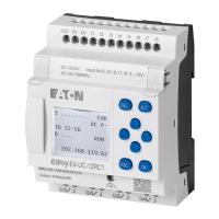
2.4.7 Connecting transistor outputs
EASY-E4-DC-... devices feature transistor outputs.
A separate power supply feed must be provided for the base device transistor out-
puts.
Q4Q3Q2Q10 V
Q
+24 V
Q
EASY-E4-DC-12TC1(P)
EASY-E4-DC-12TCX1(P)
+24 V
0 V
F2
≧ 2.5 A
Fig. 24: Connecting base device transistor outputs
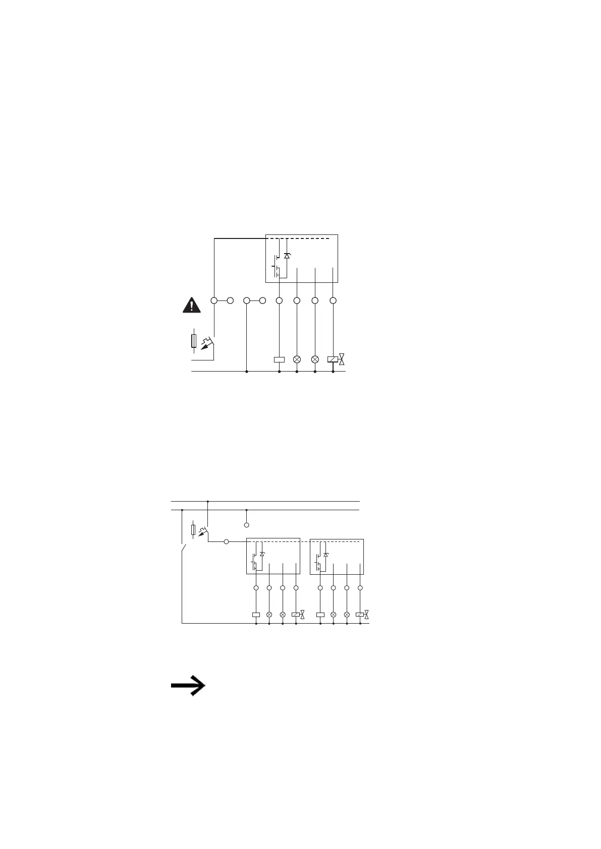
Transistor outputs on easyE4 expansion devices are powered via the power supply
for the expansion device. In other words, transistor outputs have the same potential
as the expansion device's inputs.
Q4Q3Q2Q1 Q8Q7Q6Q5
+24 V
EASY-E4-DC-8TE1(P)
EASY-E4-DC-16TE1(P)
EASY-E4-DC-16TE1(P)
F2 ≧ 2.5 A
+24 V DC
0
V
EASY-E4-DC-8TE1
F2 ≧ 5 A
EASY-E4-DC-16TE1
0 V
Fig. 25: Connecting expansion device transistor outputs
Suppressor circuit for transistor outputs on EASY-E4-...
devices.
When inductive loads without a suppressor circuit are switched off, overvoltages are
produced. Accordingly, use an appropriate suppressor circuit for the transistor out-
puts in order to handle this and prevent electronic components from overheating in
the worst-case scenario.
76
easyE402/24 MN050009ENEaton.com
 Loading...