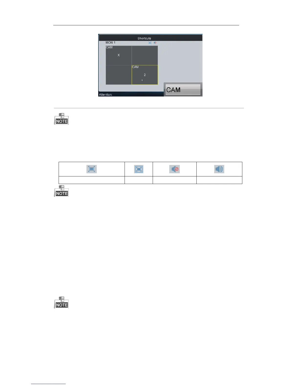
Figure 5. 5 Setting Camera to Monitor
1. The value of the monitor No. is the sum of the device segment and the window No. if B20 MVC/multi-screen
controller/64-S decoder/64-T decoder is connected. E.g. The segment of B20 MVC is 1000, and the window
No. is 1, then the value of the monitor No. is 1001.
2. Press NEXT/PREV to switch to next/previous monitor.
Description of icons:
In the local live view mode, when you input 0+MON keys, only the single-window display mode is supported.
Corresponding error message will appear on the screen when you perform wrong operation.
5.3.3 Setting Camera Group to Monitor
The video signal from the selected camera group can be outputted to and displayed by the decoding channel on
monitor.
1. When the number of cameras is equal to or less than the number of display windows on screen, e.g., 8
cameras9 windows, then each camera will be displayed on its corresponding monitor respectively, e.g.,
camera 1 on window 1, camera 8 on window 8, etc.
2. When the number of cameras is more than the number of display windows on screen, e.g., 34 cameras 16
windows, then the camera 1-16 will be displayed on window 1-16, camera 17-32 on window 1-16, and
camera 33-34 on window 1-2 in cycle view mode.
The dwell time for the cycle view is set in the input group setting interface, refer to 4.3.4 Setting Input
Group.
Steps:
1. Press the Num + MON keys to select the monitor.
2. Press the Num + CAM-G keys to select the input camera group to be decoded and displayed on the monitor.
 Loading...