Operation Manual – SNMP
Quidway S3100 Series Ethernet Switches Chapter 1
SNMP Configuration
Huawei Technologies Proprietary
1-8
1.5 SNMP Configuration Example
1.5.1 SNMP Configuration Example
I. Network requirements
z An NMS and an Ethernet switch are connected through the Ethernet. The IP
address of the NMS is 10.10.10.1 and that of the VLAN interface on the switch is
10.10.10.2.
z Perform the following configuration on the switch: setting the community name
and access authority, administrator ID, contact and switch location, and enabling
the switch to sent trap packet.
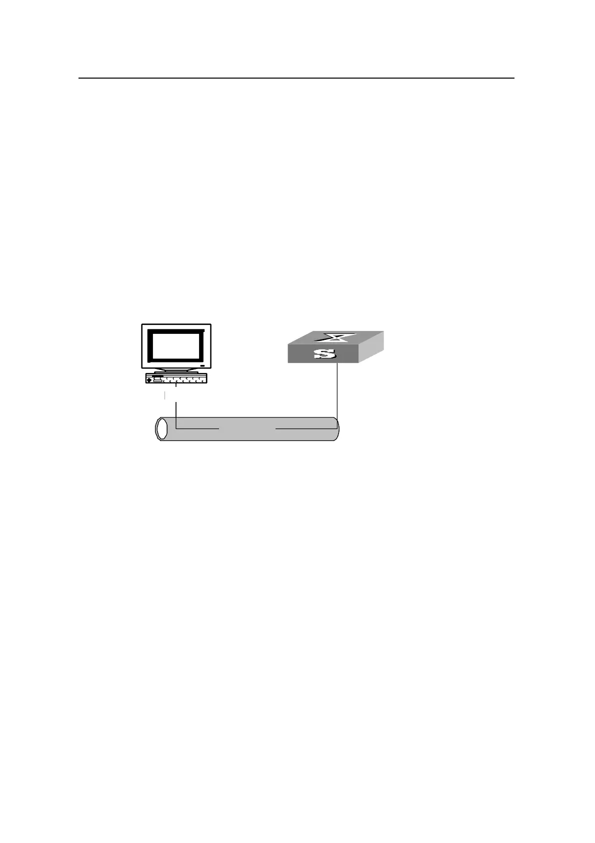
II. Network diagram
Ethernet
NMS
10.10.10.1
10.10.10 .2
Ethernet
NMS
10.10.10.1
10.10.10 .2
Figure 1-2 Network diagram for SNMP
III. Network procedure
# Set the community name, group name and user.
<Quidway> system-view
[Quidway] snmp-agent sys-info version all
[Quidway] snmp-agent community write public
[Quidway] snmp-agent mib-view include internet 1.3.6.1
[Quidway] snmp-agent group v3 managev3group write-view internet
[Quidway] snmp-agent usm-user v3 managev3user managev3group
# Set the VLAN interface 2 as the interface used by network management. Add port
Ethernet1/0/2 to the VLAN 2. This port will be used for network management. Set the IP
address of VLAN interface 2 as 10.10.10.2.
[Quidway] vlan 2
[Quidway-vlan2] port ethernet 1/0/2
[Quidway-vlan2] quit
[Quidway] interface Vlan-interface 2
[Quidway-Vlan-interface2] ip address 10.10.10.2 255.255.255.0
 Loading...