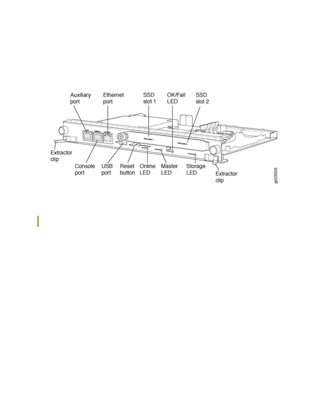
2. Plug the RJ-45 end of the serial cable into the auxiliary port or console port on an EX9200 switch.
Figure 59 on page 189 shows locaon of AUX and CONSOLE ports on an RE module in an EX9200
switch.
Figure 59: Console and Auxiliary Ports on the RE Module in an EX9200 Switch
3. Plug the socket DB-9 end into the serial port of the switch.
Connecng the EX9200 Switch to an External Alarm-Reporng Device
To connect the switch to external alarm-reporng devices, aach wires to the MAJOR ALARM and
MINOR ALARM relay contacts on the cra interface. See Figure 60 on page 190. A system condion
that triggers the major or minor alarm LED on the cra interface also acvates the corresponding alarm
relay contact.
The terminal blocks that plug into the alarm relay contacts are supplied with the switch. They accept
wire of any gauge between 28 AWG (0.08 mm
2
) and 14 AWG (2.08 mm
2
), which is not provided. Use
the gauge of wire appropriate for the external device you are connecng.
To connect an external device to an alarm relay contact (see Figure 60 on page 190):
1. Prepare the required length of wire with gauge between 28 AWG (0.08 mm
2
) and 14 AWG
(2.08 mm
2
).
2. While the terminal block is not plugged into the relay contact, use a 2.5 mm at-blade screwdriver to
loosen the small screws on its side. With the small screws on its side facing le, insert wires into the
slots in the front of the block based on the wiring for the external device. Tighten the screws to
secure the wire.
189
 Loading...