The alarm cuto/lamp test (ACO/LT) buon, located next to the alarm LEDs, is a control buon for
alarms. You can press the ACO/LT buon to deacvate major and minor alarms. Deacvang an alarm
turns o both LEDs and deacvates the device aached to the corresponding alarm relay contact on the
cra interface.
Table 12 on page 35 describes the alarm LEDs and the alarm cuto/lamp test buon.
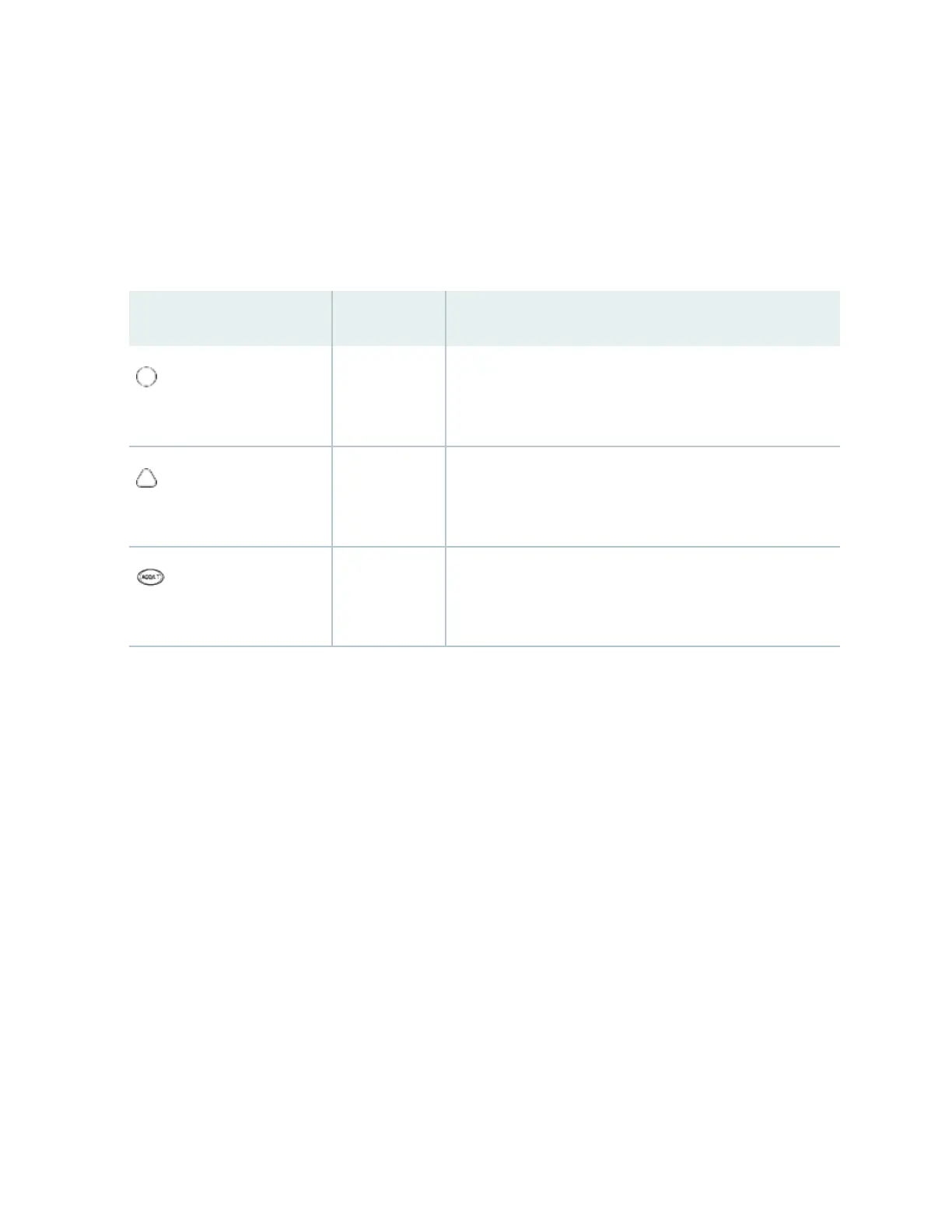
Table 12: Alarm LEDs and Alarm Cuto/Lamp Test Buon
Alarm LEDs and Buon Status Descripon
Major alarm LED
Red Indicates a crical condion that can cause the switch to stop
funconing. Possible causes include component removal,
failure, or overheang.
Minor alarm LED
Yellow Indicates a serious but nonfatal error condion, such as
warning for a maintenance or a signicant increase in
component temperature.
Alarm cuto/lamp test buon
– Deacvates major and minor alarms. Causes all LEDs on the
cra interface to light (for tesng) when pressed and held.
Alarm Relay Contacts
The cra interface has two alarm relay contacts for connecng the switch to external alarm devices.
Whenever a system condion triggers either the crical (major alarm) or warning (minor alarm) alarm on
the cra interface, the alarm relay contacts are also acvated. The alarm relay contacts are located on
the upper right of the cra interface.
35
 Loading...