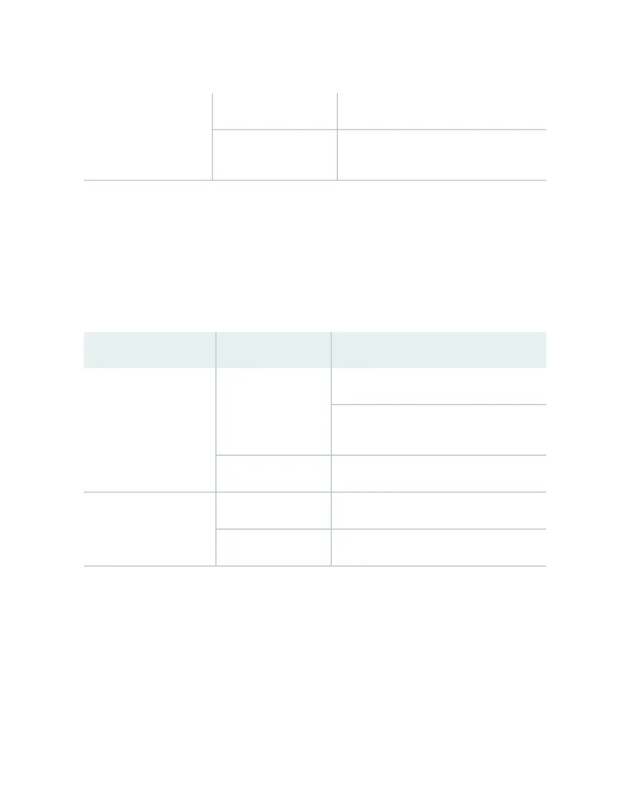
Table 10: Switch Fabric Module LEDs on the Cra Interface
(Connued)
FAIL Red The SF module has failed.
Unlit The SF module is not installed or is not
funconing normally.
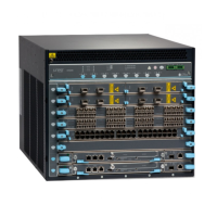
Line Card LEDs and Control Buons
Each line card has two LEDs—OK and FAIL—on the cra interface that indicates its status. The line card
LEDs are associated with control buons and are located along the boom of the cra interface. You
can turn a line card online or oine by using its control buon on the cra interface. Table 11 on page
34 describes the funcon of the line card LEDs.
Table 11: Line Card LEDs on the Cra Interface
Label Status Descripon
OK Green On steadily—Line card is funconing normally.
Blinking—Line card is coming online or going
oine.
Unlit Line card is not online.
FAIL Red Line card has failed.
Unlit Line card is not installed or funconing normally.
Alarm LEDs and Alarm Cuto Buon
Two large alarm LEDs are located at the upper right of the cra interface. The circular LED called major
alarm LED glows to indicate a crical condion that can result in a system shutdown. The triangular LED
called minor alarm LED glows to indicate a less severe condion (warning) that requires monitoring or
maintenance. Both LEDs can be lit simultaneously.
A condion that causes an LED to be lit also acvates the corresponding alarm relay contact on the cra
interface.
34
 Loading...