In the example, the assembly input object 73 is used for reading status informaon of
the inverter and the assembly output object 23 is used for controlling the inverter.
The assembly objects 73 (Extended Speed and Torque Control Input) and 23 (Extended
Speed and Torque Control Output) can be used for most of the
applicaons.
Informaon on the assembly objects: 4Objects ^ 324
Further entries:
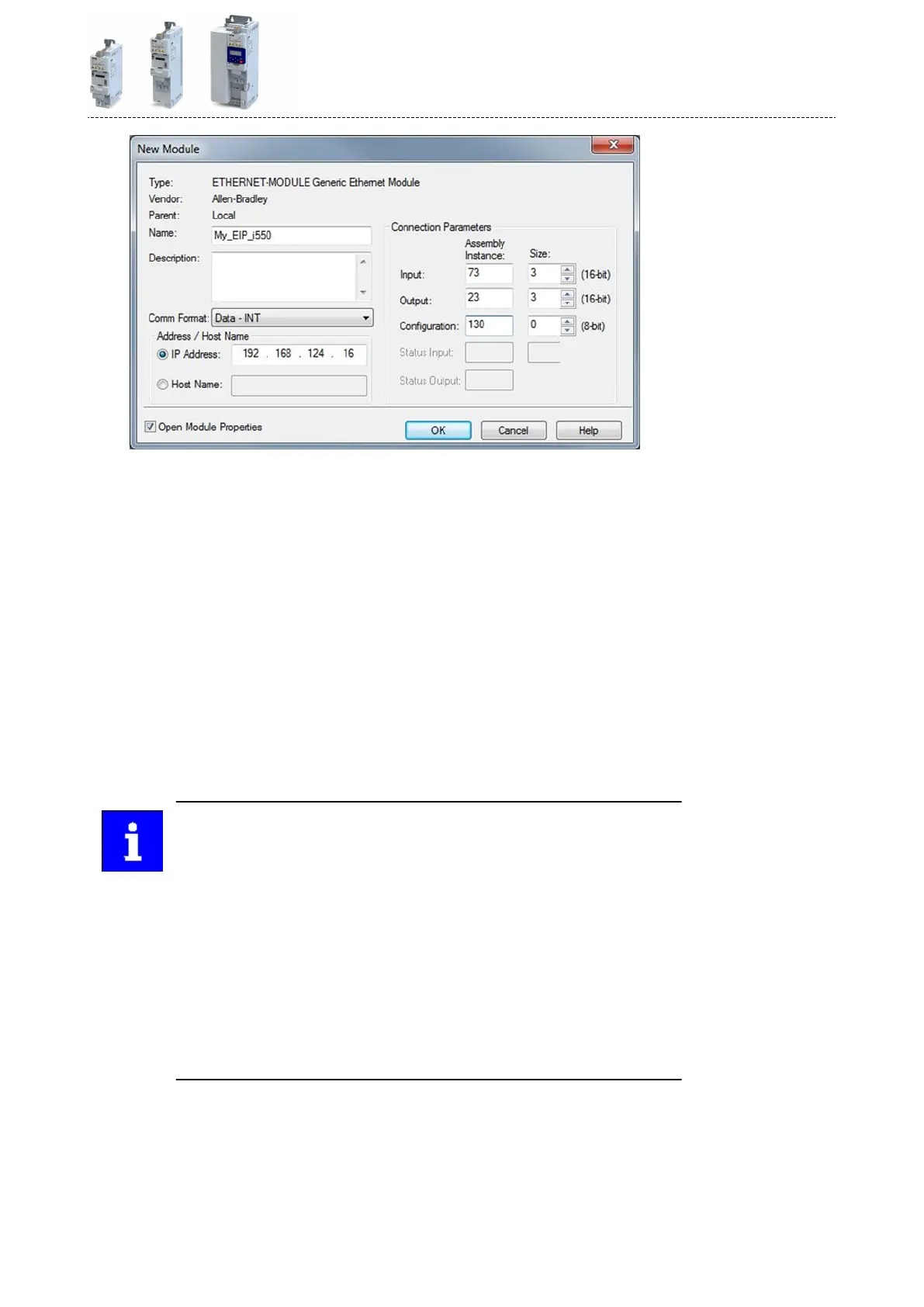
a) The name to be entered should refer to the process or the device.
b) When entering the IP address, make sure that the inverter (adapter) is in the same
network as the PLC (scanner). The subnetwork corresponds to the rst three bytes of
the IP address.
See also: 4Basic sengs ^ 317
c) Select "Data-INT" for the "Comm Format" since the data in the assembly objects 73
and 23 are given in 16-bit-integer words.
d) The required size "0" is entered for the conguraon assembly 130.
e) Size "3" is entered for the assembly input object 73.
f) Size "3" is entered for the assembly output object 23.
The inverter (adapter) must be in the same subnetwork as the PLC (scanner).
The subnetwork corresponds to the rst three bytes of the IP address.
The size of the assembly input and output objects must comply with the num-
ber of words that are actually used.
Bits 5 (NetCtrl) and 6 (NetRef) of byte 0 in the assembly output object 23 must
be transmied for the inverter in order that the control and speed reference
commands are accepted by the network.
If the network control is acve (0x400B:001 (P592.01)/bit 5 = 1 and 0x2631:037
(P400.37) = 114), all bits of the AC drive control word (0x400B:001 (P592.01))
are processed.
If the network control is not acve (0x400B:001 (P592.01)/bit 5 = 0 or
0x2631:037 (P400.37) = 0), the control bits 0, 1, 12, 13, 14, 15 are not pro-
cessed. Their states are ignored and the drive is in local control.
5. Click "OK".
The "Module Properes Report: ..." dialog box is opened.
Conguring the network
EtherNet/IP
Process data transfer
333
 Loading...


