7.5 Starng/stopping performance
7.5.1 Starng performance
The start can be oponally made with DC braking or ying restart circuit. Moreover, an auto-
mac start can be acvated aer switch-on.
Details
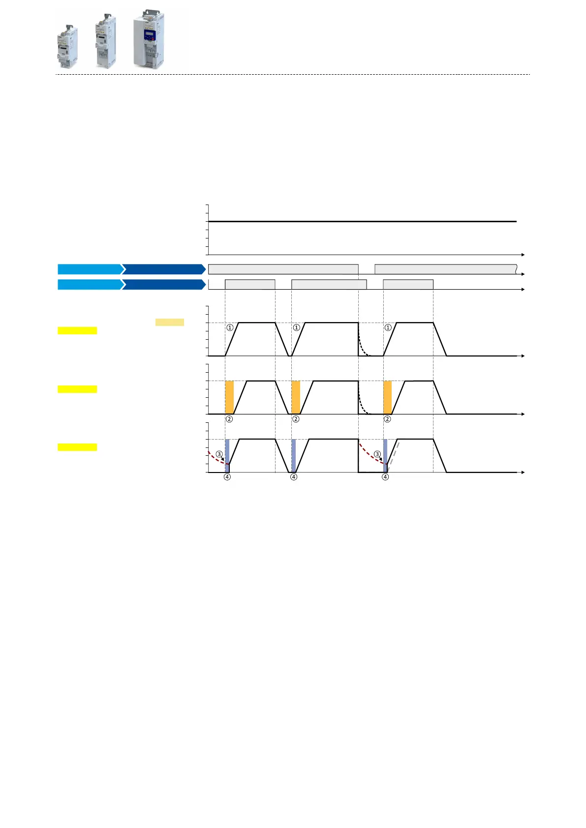
The start method can be selected in 0x2838:001 (P203.01). The following diagram demon-
strates the dierent start methods:
t
0 Hz
30 Hz
10 Hz
20 Hz
40 Hz
50 Hz
60 Hz
0 Hz
30 Hz
10 Hz
20 Hz
40 Hz
50 Hz
60 Hz
t
t
t
0 Hz
30 Hz
10 Hz
20 Hz
40 Hz
50 Hz
60 Hz
0 Hz
30 Hz
10 Hz
20 Hz
40 Hz
50 Hz
60 Hz
t
t
0x2838 001:
0x2838 001:
0x2838 001:
0x2DDD
DC brake
= Flying restart circuit [2]
= DC braking [1]
= Normal [0]
DC brake
DC brake
Digital input 2 [12] Run
Digital input 1 [11]
Output signals
Output frequency
Enable inverter
Input signals
Frequency setpoint selection
FunctionTrigger
①
Start method = "Normal [0]": Aer the start command, the motor is accelerated to the setpoint with the set acceleraon me.
②
Start method = "DC braking [1]": Aer the start command, the "DC braking" funcon is acve. Only aer the hold me set in 0x2B84:002
(P704.02) has elapsed, the motor is accelerated to the setpoint with the set acceleraon me.
4DC braking ^ 437
③
For demonstrang the ying restart circuit: At the me of the start command, the motor is not at standsll (for instance by loads with high
inera such as fans or ywheels).
④
Start method = "Flying restart circuit [2]": Aer the start command, the ying restart circuit is acve. The ying restart circuit serves to
restart a coasng motor on the y during operaon without speed feedback. The synchronicity between inverter and motor is coordinated
so that the transion to the rotang motor is eected without jerk at the me of connecon.
4Flying restart circuit ^ 481
Basic seng
Starng/stopping performance
Starng performance
153
 Loading...


