11.18.1 HTL encoder
In case of the inverter i550, the digital inputs DI3 and DI4 can be congured as HTL input to
evaluate the signal of a cost-eecve HTL encoder or a reference frequency ("pulse train").
An HTL encoder can be used at the Inverter i550 for the following tasks:
•
As motor encoder for a motor speed feedback for speed control as precise as possible.
•
As setpoint encoder for dening a frequency setpoint.
•
As setpoint encoder for dening the reference value for the process controller.
•
As setpoint encoder for dening a torque setpoint.
•
As actual value encoder for the process controller.
•
As actual value encoder for the "posion counter" funcon.
Precondions
•
Single-track or two-track HTL encoder.
•
A single-track HTL encoder (track A) cannot be used for motor speed feedback.
•
A two-track HTL encoder (track A and B) must have a phase oset of exactly 90°
between track A and B (error ≤ ±10°). Inverted tracks are not required.
•
Encoder increments: ≤ 16384 increments per revoluon
•
For supplying the encoder, the maximum supply current of the inverter must be consid-
ered. If necessary, an external 24-V voltage supply for the encoder is required.
Restricons
•
When the digital inputs DI3 and DI4 are congured as HTL input, these two digital inputs
are no longer available for other control funcons.
•
The HTL input can be either used for detecng an HTL encoder signal or a pulse train. They
cannot be used at the same me.
•
The maximum input frequency of the digital inputs is 100 kHz. If this frequency is excee-
ded, an error is triggered.
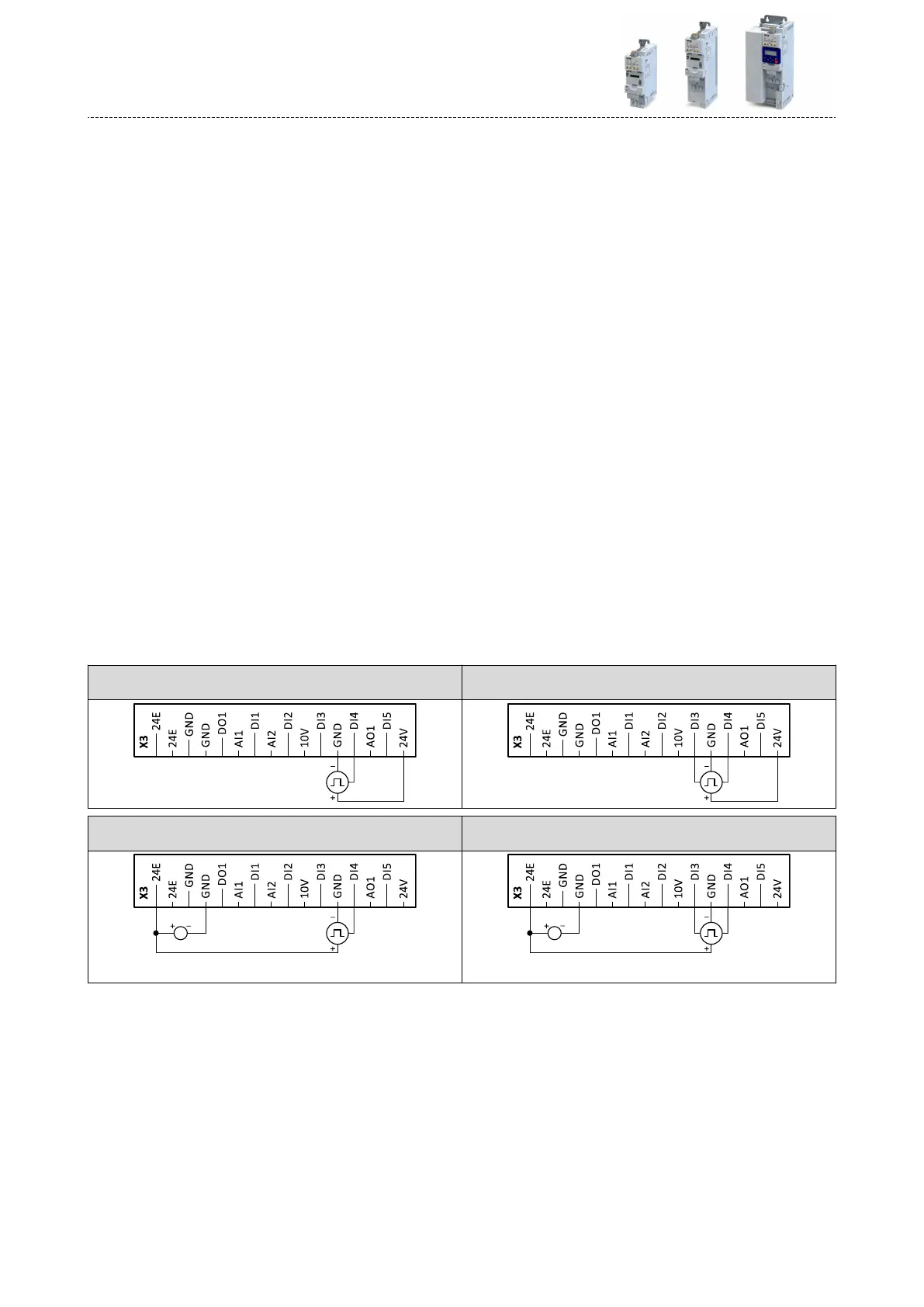
Connecon
Connecon of single-track HTL encoder
(without external 24-V voltage supply)
Connecon of two-track HTL encoder
(without external 24-V voltage supply)
Connecon of single-track HTL encoder
(with external 24-V voltage supply)
Connecon of two-track HTL encoder
(with external 24-V voltage supply)
DC 24 V SELV/PELV
(+19.2 ... +28.8 V)
A
DC 24 V SELV/PELV
(+19.2 ... +28.8 V)
B
A
Addional funcons
Encoder sengs
HTL encoder
496
 Loading...


