14.15.5.1 Example 1: Pulse train 0 ... 10 kHz ≡ output frequency 0 ... 100 Hz
In this conguraon, a pulse train is provided at the digital output 1 proporonately to the
current output frequency of the inverter (1 kHz pulse train ≡ 10 Hz output frequency, resolu-
on 0.1 Hz).
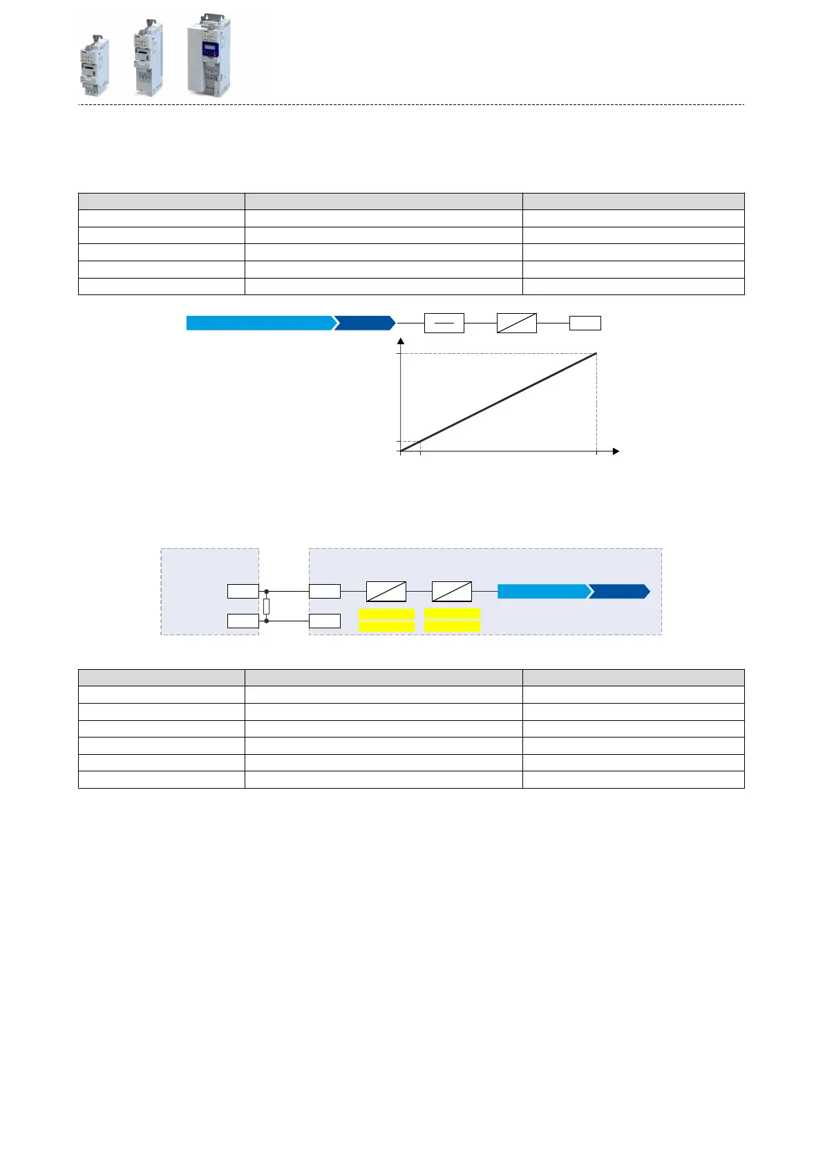
Parameter Designaon Seng for this example
0x2644:001 (P423.01) DO1 frequency setup: Minimum frequency 0.0 Hz
0x2644:002 (P423.02) DO1 frequency setup: Maximum frequency 10000.0 Hz
0x2644:003 (P423.03) DO1 frequency setup: Funcon Output frequency [1]
0x2644:004 (P423.04) DO1 frequency setup: Minimum signal 0
0x2644:005 (P423.05) DO1 frequency setup: Maximum signal 1000
1000
0
10
[0.1 Hz]0
100.0
[Hz]
1
100
10.0
DO1
X3
Hz
0x2644:003
Min
Max
Pulse train [kHz]
Output frequency [1]
Use pulse train as setpoint source for other inverters (slaves)
The pulse train can be transferred to one or several other i5xx inverters (slaves) and be cong-
ured in the respecve slave as a frequency setpoint source:
DO1
X3
GND GND
1k
DI4
0x2640:003
0x2640:001
%
Hz
0x2640:004
X3
%
Hz
0x2860:001
0x2640:002
Frequency setpoint source
HTL input [4]
Inverter (master) Inverter (slave)
For this purpose, the following sengs are required for the i5xx slave:
Parameter Designaon Seng for this example
0x2630:002 (P410.02) Sengs for digital inputs: Input funcon Pulse train [2]
0x2640:001 (P415.01) HTL input sengs: Minimum frequency 0.0 Hz
0x2640:002 (P415.02) HTL input sengs: Maximum frequency 10000.0 Hz
0x2640:003 (P415.03) HTL input sengs: Minimum motor frequency 0.0 Hz
0x2640:004 (P415.04) HTL input sengs: Maximum motor frequency 100.0 Hz
0x2860:001 (P201.01) Frequency control: Default setpoint source HTL input [4]
Flexible I/O conguraon
Conguraon of digital outputs
HTL output
615
 Loading...


