Asseron level "HIGH acve" or "LOW acve"
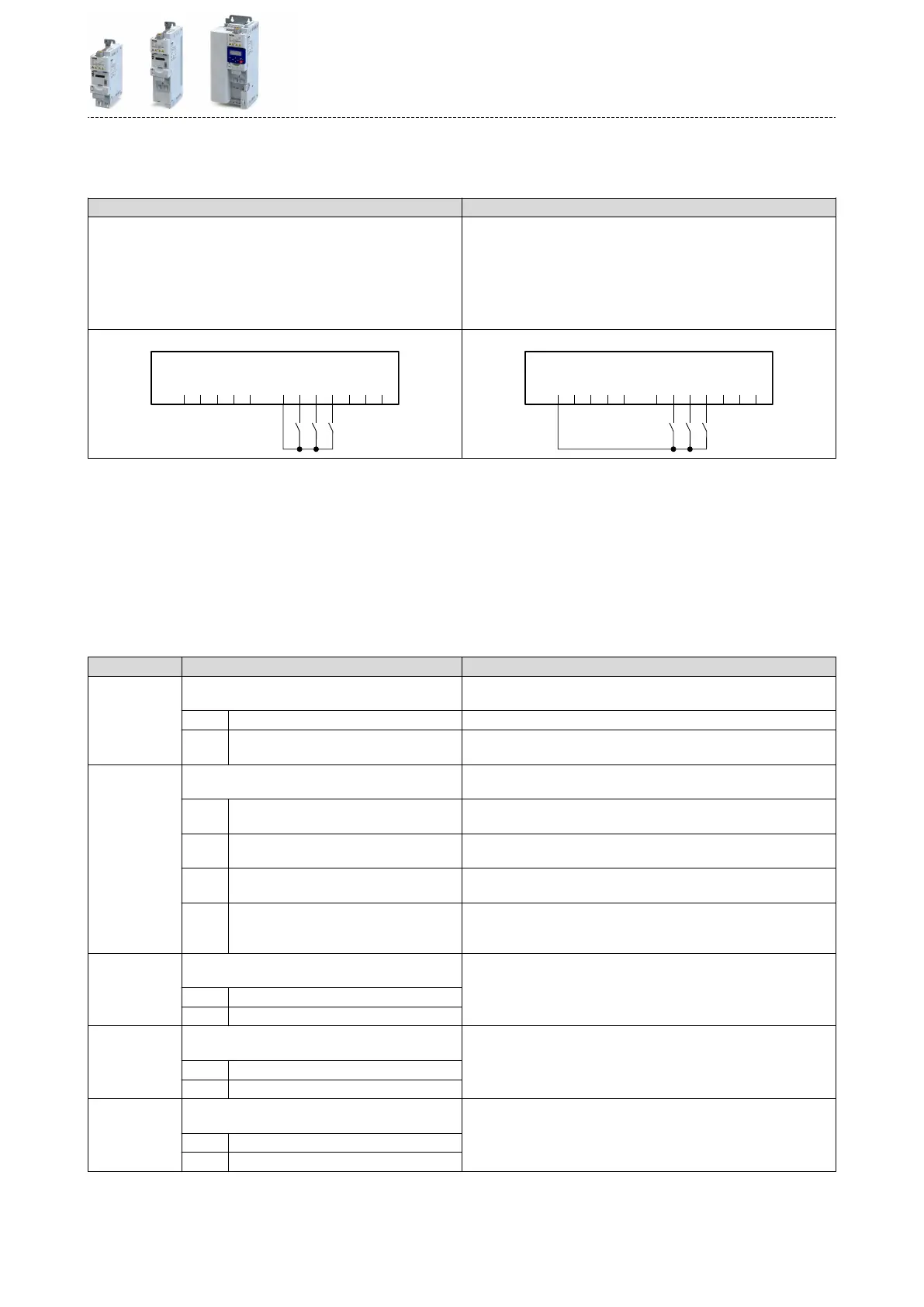
The digital inputs can be congured in 0x2630:001 (P410.01) HIGH acve (default seng) or
LOW acve:
HIGH acve (default seng) LOW acve
•
Internally, the digital input terminals are set to LOW level via pull-
down resistors.
•
The current ows from the current supply (e.g. X3/24V) through the
contact to the digital input terminal (and internally via the pull-down
resistor to GND).
•
If the contact is closed, the digital input is set to HIGH level and is thus
HIGH acve.
•
Internally, the digital input terminals are set to HIGH level via pull-up
resistors.
•
The current ows from the digital input terminal through the contact
to GND.
•
If the contact is closed, the digital input is set to LOW level and is thus
LOW acve.
Connecon plan (example): Connecon plan (example):
GND
AI1
AI2
AO1
10V
24V
DI1
DI2
DI3
DI4
DI5
DO1
X3
S1 S2 S3
GND
AI1
AI2
AO1
10V
24V
DI1
DI2
DI3
DI4
DI5
DO1
X3
S1 S2 S3
Debounce me
For minimising interference pulses, a debounce me of 1 ms is set for all digital inputs.
Via »EASY Starter« (or network), the debounce me for can be increased individually for each
digital input to maximally 50 ms.
Inversion
Each digital input can be congured in such a way that the status pending at the terminal is
internally inverted logically. This way, a closed contact, for instance, serves to deacvate an
assigned funcon instead of acvang it. Thus, the control of the inverter can be exibly
adapted to the requirements of the actual applicaon.
Parameter Name / value range / [default seng] Info
0x2630:001
(P410.01)
Sengs for digital inputs: Asseron level
(DI sengs: Asseron level)
Denion of the internal hardware interconnecon of the digital input
terminal (X3/DIx).
0 LOW acve Digital input terminals (X3/DIx) are set to HIGH level via pull-up resistors.
1 HIGH acve Digital input terminals (X3/DIx) are set to LOW level via pull-down resis-
tors.
0x2630:002
(P410.02)
Sengs for digital inputs: Input funcon
(DI sengs: Input funcon)
Input funcon of the digital terminals DI3 and DI4.
0 Digital input DI3 = digital input
DI4 = digital input
1 HTL encoder (AB) (from version 02.00) DI3 = HTL input for encoder track B
DI4 = HTL input for encoder track A
2 Pulse train (from version 03.00) DI3 = digital input
DI4 = HTL input for pulse train
3 Pulse train/direcon (from version 03.00) DI3 = HTL input for direcon specicaon; HIGH level = counter-clock-
wise (CCW)
DI4 = HTL input for pulse train
0x2632:001
(P411.01)
Inversion of digital inputs: Digital input 1
(DI inversion: DI1 inversion)
Inversion of digital input 1
0 Not inverted
1 Inverted
0x2632:002
(P411.02)
Inversion of digital inputs: Digital input 2
(DI inversion: DI2 inversion)
Inversion of digital input 2
0 Not inverted
1 Inverted
0x2632:003
(P411.03)
Inversion of digital inputs: Digital input 3
(DI inversion: DI3 inversion)
Inversion of digital input 3
0 Not inverted
1 Inverted
Flexible I/O conguraon
Conguraon of digital inputs
595
 Loading...


