4.4.2 Modbus RTU
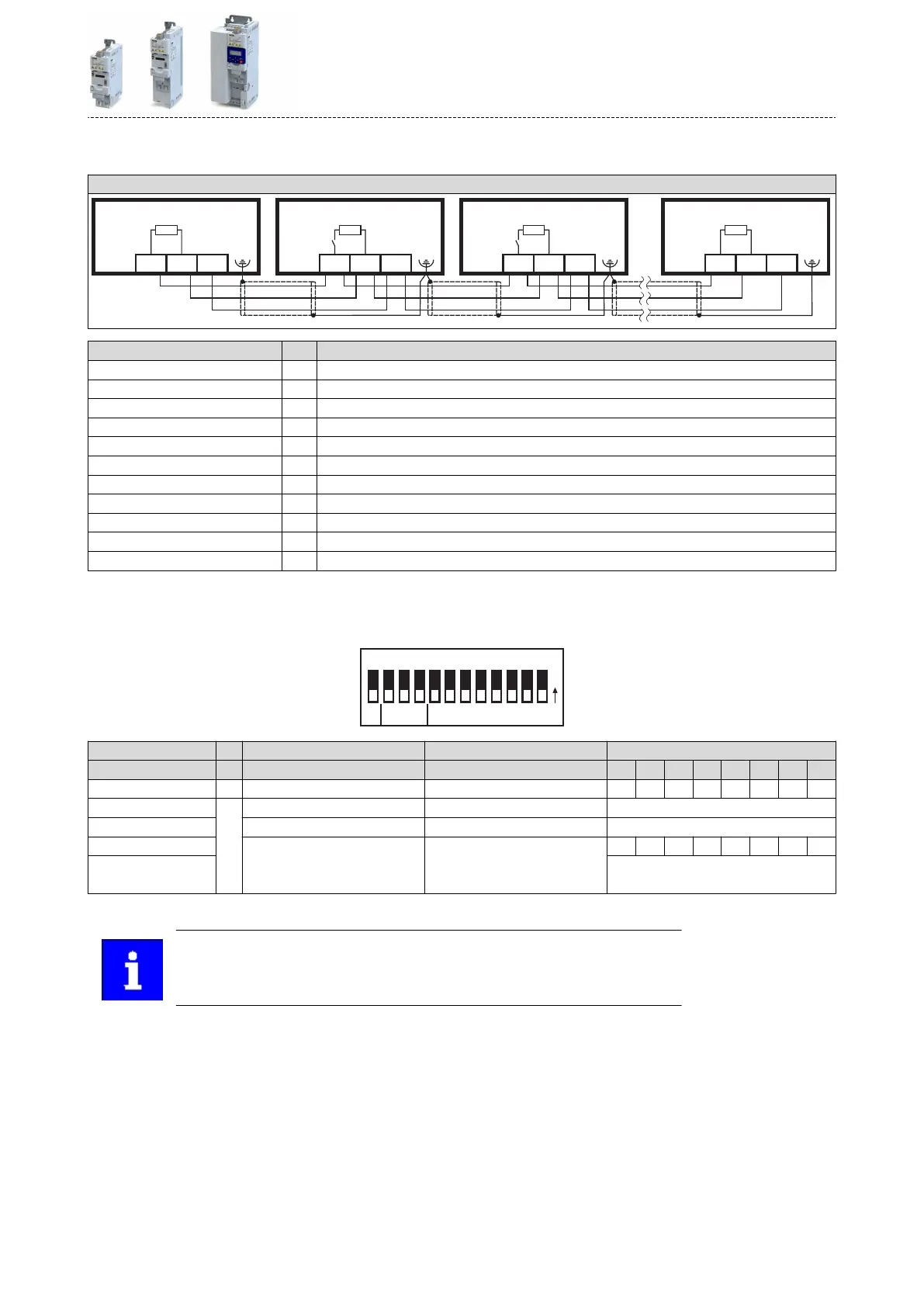
Typical topologies
Line
A1 A2 A3 An
X216 X216 X216 X216
120 120 120 120
COM COM COM COM
TB TB TB TB
TA TA TA TA
Terminal descripon Modbus RTU
Connecon X216
Connecon type pluggable spring terminal
Min. cable cross-secon mm² 0.5
Min. cable cross-secon AWG 22
Max. cable cross-secon mm² 2.5
Max. cable cross-secon AWG 12
Stripping length mm 10
Stripping length inch 0.39
Tightening torque Nm -
Tightening torque lb-in -
Required tool 0.4 x 2.5
Basic network sengs
Use the DIP switch to set the node address and baud rate and to acvate the integrated bus
terminang resistor.
Mode Address
O
N
R
64 32 16 8
421
b a 128c
Bus terminaon Baud rate Parity Modbus node address
R c b a 128 64 32 16 8 4 2 1
OFF n.c. OFF OFF OFF OFF OFF OFF OFF OFF OFF OFF
Inacve Automac detecon Automac detecon Value from parameter
ON
ON ON Node address - example:
Acve
Value from parameter Value from parameter OFF OFF OFF ON OFF ON ON ON
Node address = 16 + 4 + 2 + 1 = 23
Node address > 247: value from parameter
Bold print = default seng
The network must be terminated with a 120 Ω resistor at the physically rst and
last node.
Set the "R" switch to ON at these nodes.
Electrical installaon
Networks
Modbus RTU
65
 Loading...


