11.9.1 Example: Selecve control of several motors with one inverter
A typical applicaon for the parameter change-over is an applicaon/machine in which sev-
eral axes must be triggered successively but a simultaneous operaon of several motors is not
required. In this case, one and the same inverter can trigger the motors in succession. Advan-
tages of this soluon are the reduced amount of components (inverters) and thus a reduced
energy consumpon.
Principle:
•
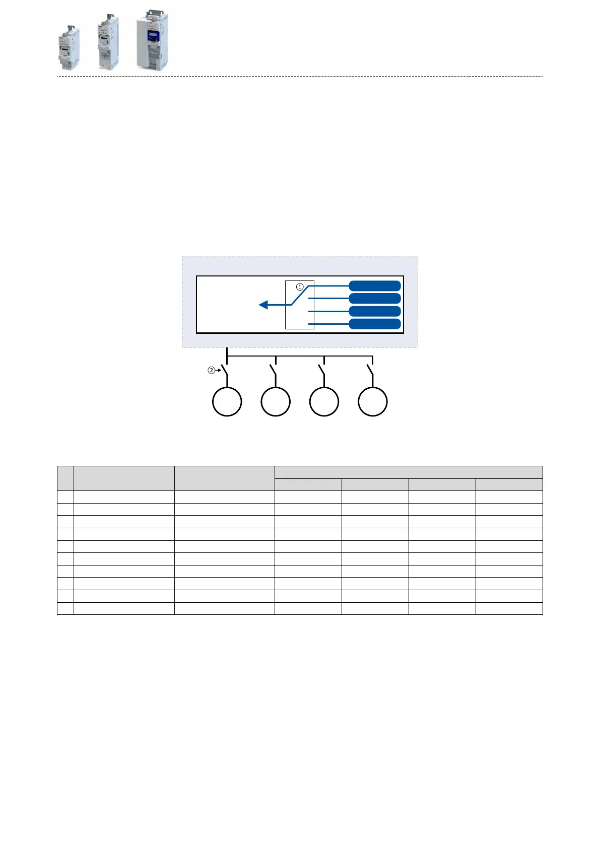
The motor to be currently controlled is connected to the inverter via motor contactors.
(The contactor system can, for instance, be controlled via the digital outputs of the inver-
ter.)
•
At the same me, the motor and control sengs suitable for motor are acvated in the
inverter by means of parameter change-over. 4Funcons for parameter change-over
^ 579
M1
3~
M2
3~
M3
3~
M4
3~
Set 4
Set 3
Set 2
Set 1
Inverter
RAM
memory
①
Motor data change-over (via the "parameter change-over" funcon)
②
Motor change-over (e.g. via motor contactors)
The following table lists all parameters that require dierent sengs for the four motors:
# Parameter Name Seng
M1 M2 M3 M4
1 0x2B00 (P302.00) V/f characterisc shape Linear [0] Square-law [1] Linear [0] Linear [0]
2 0x2B01:002 (P303.02) Base frequency 60 Hz 60 Hz 60 Hz 50 Hz
3 0x2D4B:001 (P308.01) Maximum ulisaon [60 s] 150 % 120 % 150 % 150 %
4 0x2B12:001 (P316.01) Fixed boost 2.5 % 0.0 % 4.0 % 2.0 %
5 0x2C01:004 (P320.04) Rated speed 1745 3450 1750 1450
6 0x2C01:005 (P320.05) Rated frequency 60.0 Hz 60.0 Hz 60.0 Hz 50.0 Hz
7 0x2C01:006 (P320.06) Rated power 0.75 kW 0.75 kW 0.75 kW 1.50 kW
8 0x2C01:007 (P320.07) Rated voltage 480 V 480 V 480 V 400 V
9 0x6075 (P323.00) Motor rated current 2,200 A 2,100 A 2,200 A 3,500 A
10 0x6073 (P324.00) Max current 200.0 % 150.0 % 200.0 % 200.0 %
Addional funcons
Parameter change-over
Example: Selecve control of several motors with one inverter
467
 Loading...


