Malfunctions during crane operation
14.7 Hydraulic emergency operation as per DGUV
Operating manual 3 302 819 en 14 - 63
GMK3060
13.12.2018
14.7.6 Establishing the required hydraulic circuits
To establish a hydraulic circuit you must switch over certain valves and may need
to perform additional switching operations.
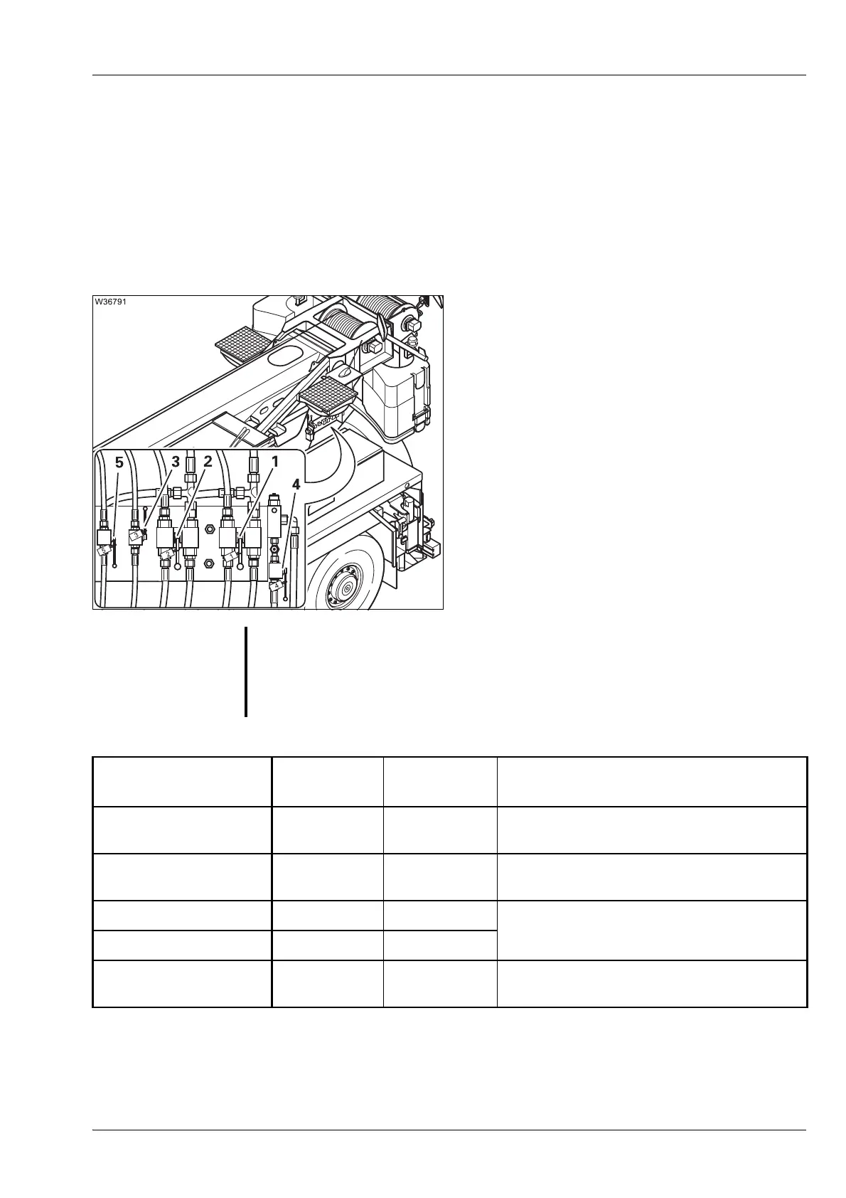
Valves at the
control panel
The valves 1 to 5 are labelled with their respective numbers.
For emergency operation
• Switch the valve 1 to 5 to the positions for the
required crane movement – as shown in the
following table.
To raise the boom, for example, you must switch
valve 3 upwards. Valves 1, 2, 4 and 5 must point
down.
s
G
Danger from mutual interference of the power units!
For one crane movement, always switch valves upward.
This prevents wrong crane movements being performed and several movements
being performed unintentionally at the same time.
Emergency operation
for crane movements
Valves
upwards
Valves
downward
Additional switching operations
Lifting 1 2, 3, 4, 5
Valve Y1105 on continuous operation;
à p. 14 - 64
Lowering 1 2, 3, 4, 5
Valve Y1104 on continuous operation;
à p. 14 - 65
Raising the boom 3 1, 2, 4, 5
None
Lowering the boom 5 1, 2, 3, 4
Slewing to the left or
right
2, 4 1, 3, 5 Valves 6, 7, 8 closed;
à p. 14 - 65

 Loading...


