2.1.3 SAFETY: Other Tips
Keep these instructions at hand, near the place of use.
Keep your workplace tidy.
Apply technical common sense: If you suspect that it is unsafe to use the product, do
the following:
Disconnect the supply voltage from the unit.
Clearly mark the equipment to prevent its further operation.
2.2 Installation Overview
The steps that need to be performed prior to putting VersaSync into service include:
Installation: Hardware setup, mechanical installation, physical connections.
Setup: Establish basic access to the unit, so as to allow the use of the web user inter-
face ("WebUI").
Configuration: Access the Web UI, configure the network, input and output ref-
erences, protocols (e.g., NTP), other settings.
Not all of the setup steps described in this manual may apply to you. Your unit installation
relative to other connected devices, the cable selection and manufacturing, your chosen
power source, your project-specific infrastructure, and your planned access to your unit
(either WebUI or CLI), could all affect your setup needs.
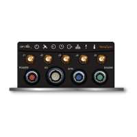
2.2.1 Hardware Connections
During the procedure described below, you will connect the Power cable, the Multi I/O
cable, and the Ethernet cable.
The step-by-step instructions below outline the VersaSync installation and configuration
process:
1.
Install VersaSync in the designated vehicle:
The mounting plate should be in direct contact with the unit base plate, so as
to conduct heat.
For more detail on mounting your unit, see "Mounting" on page28.
2.
Connect the power supply. The unit will power up, and the ON/OFF status LED
will pulsate.
26
CHAPTER 2 • VersaSync User Manual Rev. 7.0
2.2 Installation Overview
 Loading...