Using the I/O 5-17
PowerFlex® 755 Drive Embedded EtherNet/IP Adapter User Manual
Publication 750COM-UM001A-EN-P
Table 5.F Program and Controller Data Table Address Descriptions for Example
Logic Command/Reference Ladder Logic Program
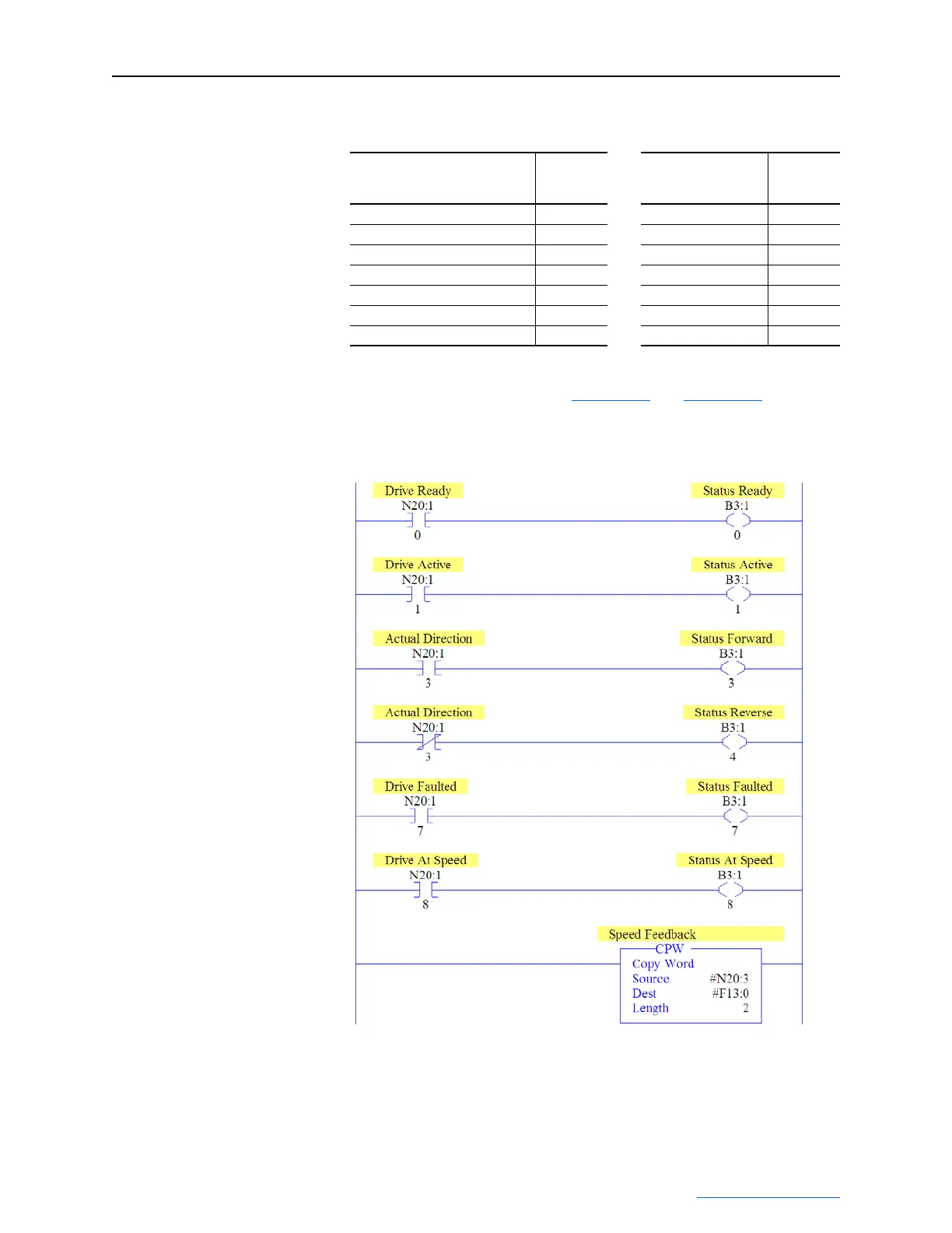
An example ladder logic program that uses these alternate controller
data table addresses is shown in Figure 5.12
and Figure 5.13.
Figure 5.12 PLC-5, SLC 500, and MicroLogix 1100 Example Ladder Logic
Program for Logic Status/Feedback
Important:This ladder does not include logic for Datalinks. However,
if Datalinks are required and they are a REAL (floating
point) data type, a data conversion must be used. For
MicroLogix 1100 controllers only, use a CPW (Copy
Description
Program
Data Table
Address
Description
Controller
Data Table
Address
Command Stop B3:20/0 Drive Stop N20:20/0
Command Start B3:20/1 Drive Start N20:20/1
Command Jog B3:20/2 Drive Jog N20:20/2
Command Clear Faults B3:20/3 Drive Clear Faults N20:20/3
Command Forward Reverse (XIO) B3:20/4 Drive Forward N20:20/4
Command Forward Reverse (XIC) B3:20/4 Drive Reverse N20:20/5
Speed Reference N30:22 Speed Reference N20:22

 Loading...