Configuring the I/O 4-33
PowerFlex® 755 Drive Embedded EtherNet/IP Adapter User Manual
Publication 750COM-UM001A-EN-P
Creating SLC 500 Ladder Logic for the Logic Status, Feedback, and DL From
Net Datalinks
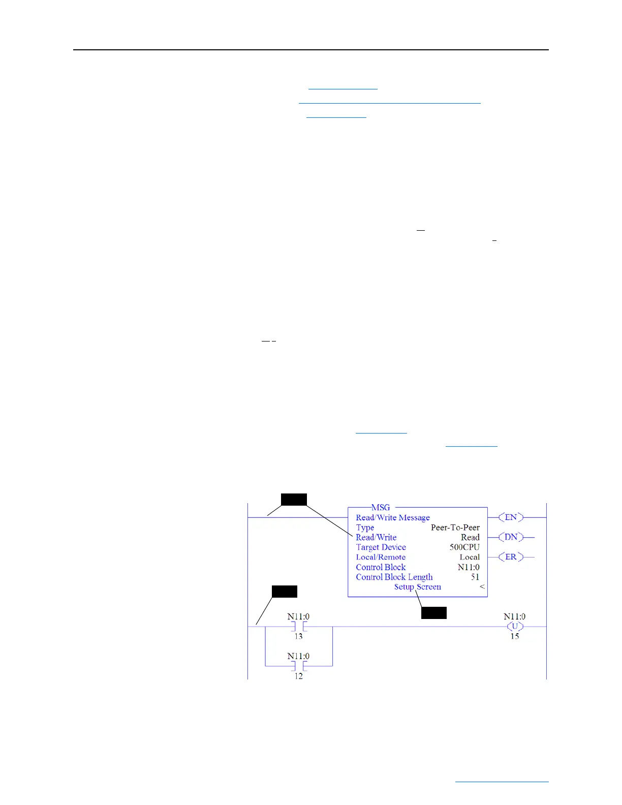
1. Insert another separate rung, double-click on the rung to display the
rung editor, and enter MSG READ 500CPU LOCAL Nxx:n,
where:
xx is an unused data file number (for example, N11:n), and
n is an unused element of the data file chosen for xx (for example, N11:0
)
Then press Enter.
2. Insert another separate rung, double-click on the rung to display the
rung editor, and enter BST XIC Nxx:n/13 NXB XIC Nxx:n/12
BND OTU Nxx:n/15, where:
xx and n must correspond to the assigned data file number and element (for example,
N11
:0) for the message created in Step 1.
Important:The information must be entered with appropriate
numbers for “xx” and “n” for your application, and
with spaces and forward slashes exactly as shown.
Then press Enter.
3. In the MSG instruction (Figure 4.37
), double-click on Setup Screen
to launch the message configuration screen (Figure 4.38
).
Figure 4.37 SLC 500 Ladder Logic for the Logic Status, Feedback, and DL
From Net Datalinks
4. Configure the General tab by entering or verifying the information
shown in the screen.
(1)
For details on data table addresses for this example project, refer to Table 5.D on page 5-15.
(2)
For details to determine element size for a specific drive, refer to Understanding Controller Data Table Addresses on page 5-14.
(3)
For details on setting the control timeout value and its function, see N-Files on page C-8.
Step 1
Step 2
Step 3

 Loading...