EasyManua.ls Logo

Rockwell Automation PowerFlex 755 Drive User Manual

Rockwell Automation PowerFlex 755 Drive
232 pages
To Next Page IconTo Next Page
To Previous Page IconTo Previous Page
Page #118 background imageLoading...
Page #118 background image
6-16 Using Explicit Messaging
PowerFlex® 755 Drive Embedded EtherNet/IP Adapter User Manual
Publication 750COM-UM001A-EN-P
PLC-5 Example Ladder Logic Program to Write Single Parameter
A Generic Set Attribute Single message is used to write to a single
parameter. This write message example writes a value to the 32-bit
REAL (floating point) parameter 535 - [Accel Time 1] in a PowerFlex
750-Series drive.
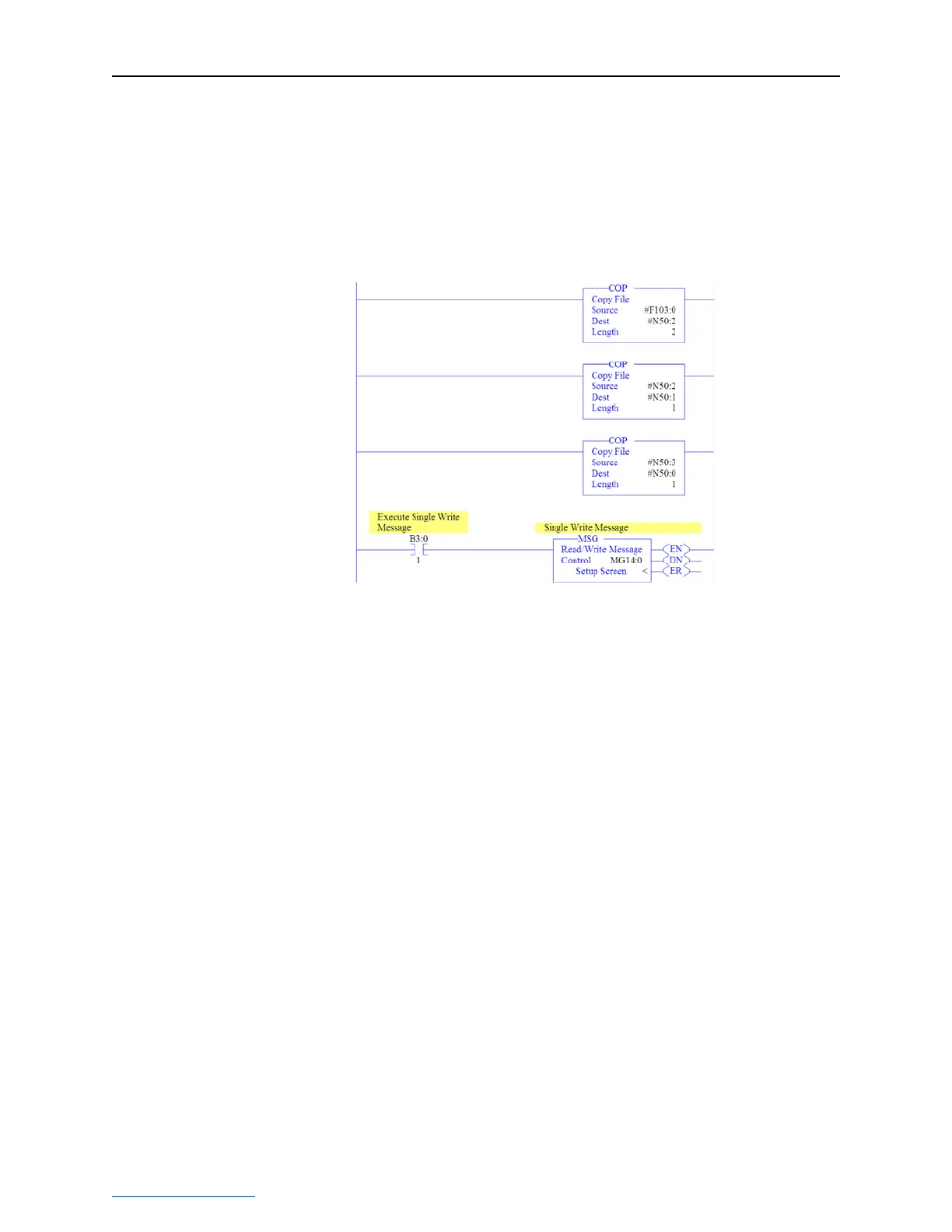
Figure 6.18 Example Ladder Logic Explicit Messaging Program for Write Single
Three COP (Copy) instructions are required to convert the 16-bit integer
data table addresses N50:0 (Least Significant Word) and N50:1 (Most
Significant Word) to a 32-bit REAL (floating point) data table address
F103:0 for correct presentation. The first COP instruction correctly
writes the 32-bit REAL (floating point) value. The second and third
COP instructions swap the LSW and MSW.

Table of Contents

Question and Answer IconNeed help?

Do you have a question about the Rockwell Automation PowerFlex 755 Drive and is the answer not in the manual?

Rockwell Automation PowerFlex 755 Drive Specifications

General IconGeneral
Frequency Range0-400 Hz
Input Voltage380-480V AC
Power Range0.75-250 kW
Output PowerVaries with model
CurrentVaries with model
Communication ProtocolsControlNet, DeviceNet, EtherNet/IP, Modbus TCP/IP, PROFIBUS
Enclosure TypeIP20, IP30, IP54 (depending on model)
SafetySafe Torque-Off
Protection FeaturesOvercurrent, Overvoltage, Undervoltage, Overtemperature, Short Circuit
DimensionsVaries with model
Control MethodsV/Hz, Sensorless Vector, Flux Vector

Summary

PowerFlex 755 Drive Embedded EtherNet/IP Adapter User Manual

Important User Information

Provides critical information for applying, installing, and maintaining the equipment, including safety guidelines and definitions of warning statements.

Safety Precautions and Definitions

Defines safety terms like WARNING, ATTENTION, Shock Hazard, and Burn Hazard, outlining potential risks and precautions.

Chapter 1 Getting Started

Safety Precautions

Outlines essential safety warnings and precautions to prevent injury or equipment damage during installation and operation.

Quick Start

Provides a step-by-step guide for experienced users to quickly begin using the embedded EtherNet/IP adapter.

Chapter 2 Installing the Adapter

Setting the IP Address Switches

Describes methods for configuring the adapter's IP address using rotary switches.

Connecting and Applying Power

Guides the user through connecting the adapter to the network and applying power to the drive.

Commissioning the Adapter

Outlines the final steps for setting up the adapter after installation and power application.

Chapter 3 Configuring the Adapter

Using BOOTP

Explains how to use the BOOTP protocol to automatically configure the adapter's network settings.

Setting Network Address Parameters

Details how to manually set the IP address, subnet mask, and gateway address using adapter parameters.

Selecting Master-Slave or Peer-to-Peer Hierarchy

Explains how to configure the communication hierarchy for the adapter.

Setting a Fault Action

Defines how the adapter and drive respond to communication disruptions or controller status changes.

Resetting and Restoring Adapter Parameters

Covers procedures for resetting the adapter and restoring its parameters to factory defaults.

Chapter 4 Configuring the I/O

Limitations with PLC-5, SLC 500, MicroLogix 1100

Highlights limitations when using older controllers with explicit messaging for I/O control.

Chapter 5 Using the I/O

Chapter 6 Using Explicit Messaging

Performing Explicit Messages

Outlines the basic events involved in the Explicit Messaging process.

ControlLogix Example

Provides examples of using Explicit Messaging with a ControlLogix controller.

PLC-5 Example

Demonstrates using Explicit Messaging with a PLC-5 controller.

SLC 500 Example

Illustrates using Explicit Messaging with an SLC 500 controller.

MicroLogix 1100 Example

Shows how to use Explicit Messaging with a MicroLogix 1100 controller.

Chapter 7 Troubleshooting

Understanding the Status Indicators

Explains how to interpret the adapter's status indicators for diagnosing problems.

Chapter 8 Viewing the Adapter Web Pages

Accessing the Adapter Web Home Page

Instructions on how to access and view the adapter's web interface.

Appendix B Adapter Parameters

Related product manuals