4-42 Configuring the I/O
PowerFlex® 755 Drive Embedded EtherNet/IP Adapter User Manual
Publication 750COM-UM001A-EN-P
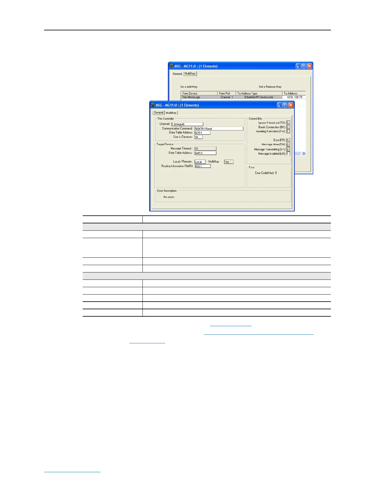
Figure 4.46 MicroLogix 1100 Message Configuration Screens for the Logic
Status, Feedback, and DL From Net Datalinks
General Tab Box Setting
This Controller (data for MicroLogix 1100)
Channel 1 (integral). Controller port to which the EtherNet/IP network is connected.
Communication Command 500CPU Read. The controller type and command type for the controller to read or write data.
Since the MicroLogix 1100 is part of the SLC-500 controller family, the “500CPU” controller
type was selected. The “Read” command type was selected to read data from the drive.
Data Table Address
(1)
N20:1. An unused controller data table address containing the data to be read from the drive.
Size in Elements
(2)
36. Number of elements (words) to be transferred. Each element size is a 16-bit integer.
Target Device (data for adapter/drive)
Message Timeout 5. Message timeout duration in seconds.
Data Table Address
(3)
N45:0. Specific starting address of the source file in the drive.
Routing Information File RI9:1. An unused routing information file for the controller.
MultiHop Tab Box Setting
To Address 10.91.100.79. The IP address of the adapter connected to the drive.
(1)
For details on data table addresses for this example project, refer to Table 5.D on page 5-15.
(2)
For details to determine element size for a specific drive, refer to Understanding Controller Data Table Addresses on page 5-14.
(3)
For N-File details, see N-Files on page C-8.

 Loading...