Using Explicit Messaging 6-11
PowerFlex® 755 Drive Embedded EtherNet/IP Adapter User Manual
Publication 750COM-UM001A-EN-P
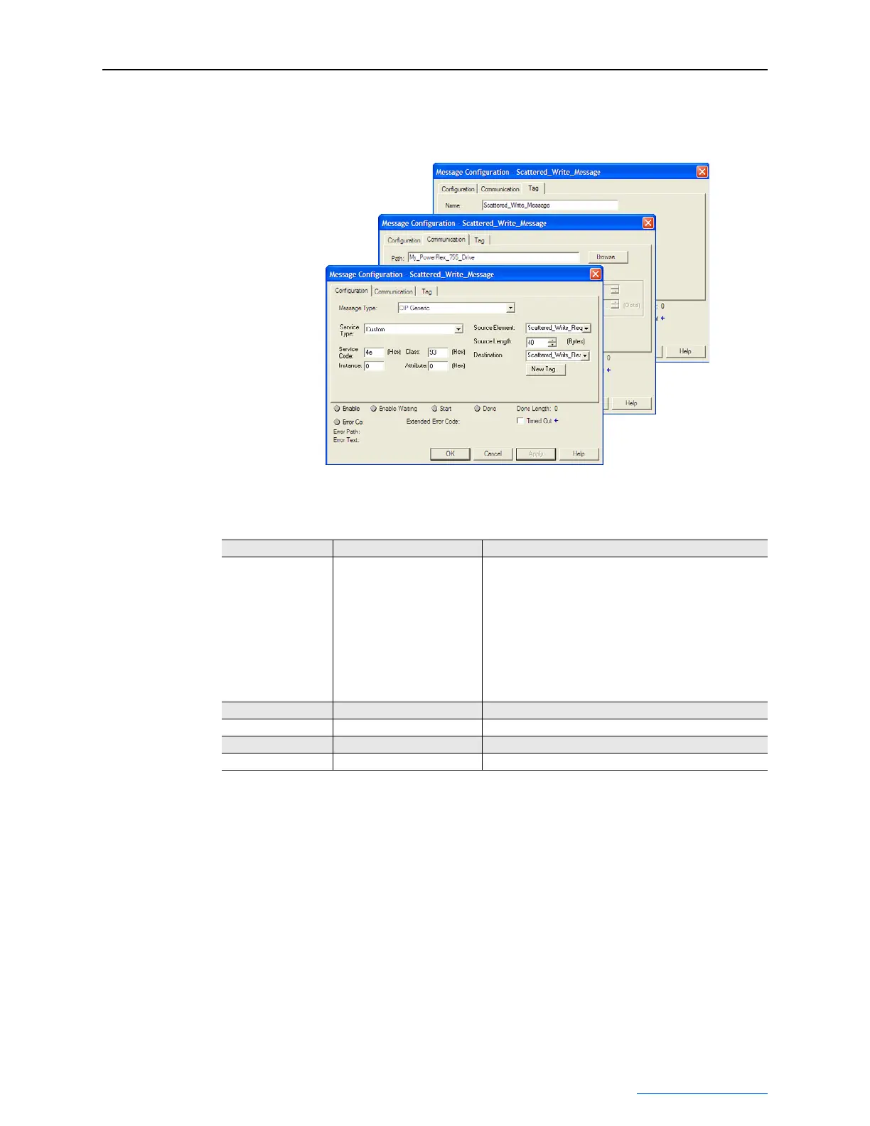
ControlLogix – Formatting a Message to Write Multiple Parameters
Figure 6.11 Scattered Write Multiple Message Configuration Screens
The following table identifies the data that is required in each box to
format a multiple write message.
Configuration Tab Example Value Description
Message Type
Service Type
(1)
Service Code
(1)
Class
Instance
Attribute
Source Element
Source Length
Destination
CIP Generic
Custom
4e (Hex.)
93 (Hex.)
0 (Dec.)
0 (Hex.)
Scattered_Write_Request
(3)
40 bytes
(3)
Scattered_Write_Response
(4)
Used to access Parameter Object in the adapter.
Required for scattered messages.
Code for the requested service.
Class ID for the DPI Parameter Object.
Required for scattered messages.
Required for scattered messages.
Name of the tag for any service data to be sent from scanner
or bridge to the adapter/drive.
Number of bytes of service data to be sent in the message.
The tag where the data that is read is stored.
Communication Tab Example Value Description
Path
(2)
My_PowerFlex_755_Drive The path is the route that the message will follow.
Tag Tab Example Value Description
Name Scattered_Write_Message The name for the message.
(1)
The default setting for Service Type is “Custom,” enabling entry of a Service Code not available from the Service Type pull-down
menu. When selecting a Service Type other than “Custom” from the pull-down menu, an appropriate Hex. value is automatically
assigned to the Service Code box which grays out (unavailable). When writing to 32-bit REAL (floating point) parameters, as in
this example, data conversion using COP (Copy) instructions or UDDT’s is required to correctly write the parameter values.
(2)
Click Browse to find the path, or type in the name of the device listed in the I/O Configuration folder (for this example,
My_PowerFlex_755_Drive).
(3)
In this example, we are writing to five 32-bit REAL (floating point) parameters. Each parameter being written to requires two
contiguous DINT registers. Therefore, a controller tag was created with its Data Type field set to the name of the UDDT of five
interleaved DINTs and REALs. Also, the Source Length field on the Message Configuration screen must correspond to the selected
Data Type in bytes (for this example, 40 bytes for an array of five scattered read structures. Scattered write messages always assume
that every parameter being written to is a 32-bit parameter, regardless of its actual size. Maximum message length is 256 bytes
which can write up to 32 parameters, regardless of their size.
(4)
The controller tag for “Scattered_Write_Response” must be the same size as the controller tag for “Scattered_Write_Request” (for
this example, 40 bytes). An array of DINTs is suggested to be able to read any error codes that are returned.

 Loading...