Configuring the Adapter 3-13
PowerFlex® 755 Drive Embedded EtherNet/IP Adapter User Manual
Publication 750COM-UM001A-EN-P
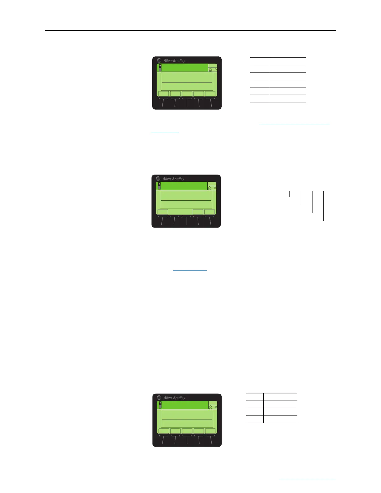
Figure 3.13 Edit Peer Flt Action HIM Screen
For more details about fault action, see Setting a Fault Action on
page 3-14.
6. Set Parameters 81 - [Fr Peer Addr 1] through 84 - [Fr Peer Addr
4] to the IP address of the drive transmitting the custom Peer I/O.
Figure 3.14 Edit Fr Peer Addr 1 Screen on the HIM
7. If a Logic Command is being sent, use Parameter 78 - [Logic Src
Cfg] to set the Datalink number containing the Logic Command.
Otherwise, set Parameter 78 to a value of “0.” For bit definitions,
refer to Appendix
D or the drive documentation.
8. If a Reference is being sent, use Parameter 79 - [Ref Src Cfg] to
set the Datalink number containing the Reference. Otherwise, set
Parameter 79 to a value of “0.”
9. In each PowerFlex 750-Series slave drive, set drive parameter 308 -
[Direction Mode] to “1” (Bipolar) to ensure that it properly follows
the master drive’s speed reference and commanded direction.
10. Reset the adapter by power cycling the drive or by using the HIM’s
Reset Device function located in the drive’s DIAGNOSTIC folder
so that changes to Parameter 76 - [DLs Fr Peer Cfg] take effect.
11. Set Parameter 85 - [Fr Peer Enable] to a value of “2” (Custom).
Figure 3.15 Edit Fr Peer Enable HIM Screen
Value Description
0 Fault (Default)
1Stop
2 Zero Data
3 Hold Last
4 Send Flt Cfg
ESC
ENTER
Stopped
0.00 Hz
AUTO
F
▲▼
Edit Peer Flt Action
Fault 0
0<<4
Default = 0.0.0.0
255 . 255 . 255 . 255
[Peer Inp Addr 1]
[Peer Inp Addr 2]
[Peer Inp Addr 3]
[Peer Inp Addr 4]
IP Address of Node Transmitting Custom Peer I/O
Edit Fr Peer Addr 1
0
0 << 255
ESC
ENTER
Stopped
0.00 Hz
AUTO
F
Value Setting
0 Off (Default)
1Cmd/Ref
2Custom
ESC
ENTER
Stopped
0.00 Hz
AUTO
F
▲▼
Edit Fr Peer Enable
Off 0
0<<2

 Loading...