EasyManua.ls Logo

Rockwell Automation PowerFlex 755 Drive User Manual

Rockwell Automation PowerFlex 755 Drive
232 pages
To Next Page IconTo Next Page
To Previous Page IconTo Previous Page
Page #142 background imageLoading...
Page #142 background image
6-40 Using Explicit Messaging
PowerFlex® 755 Drive Embedded EtherNet/IP Adapter User Manual
Publication 750COM-UM001A-EN-P
MicroLogix 1100 – Formatting a Message to Write Multiple
Parameters
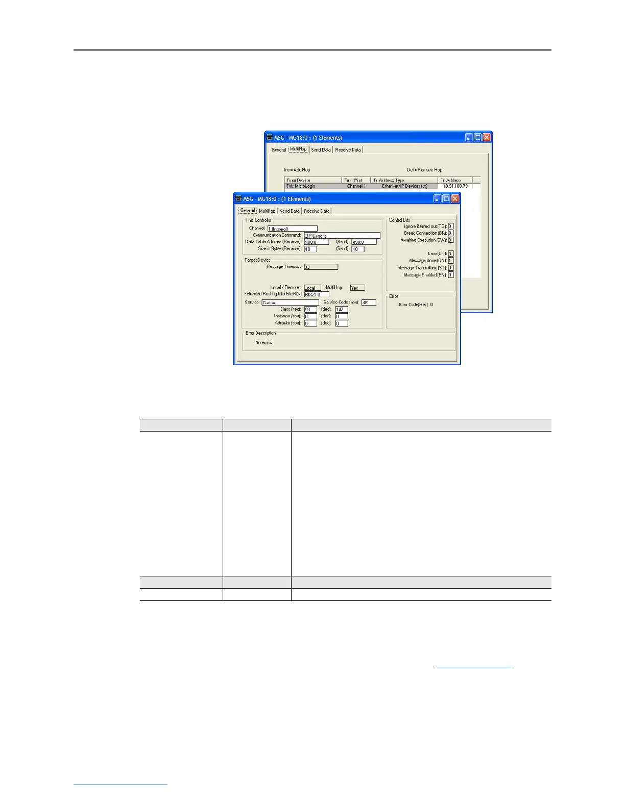
Figure 6.48 Custom Scattered Write Multiple Message Configuration Screens
The following table identifies the data that is required in each box to
format a multiple write message.
General Tab Example Value Description
Channel
Comm… Command
Data Table Address
Receive
Send
Size in Bytes
Receive
Send
Extended Routing…
Service
(1)
Service Code
Class
Instance
Attribute
1
CIP Generic
N80:0
N90:0
40
(2)
40
(2)
RIX21:0
Custom
4E (Hex.)
(3)
93 (Hex.)
0 (Dec.)
0 (Dec.)
Controller port to which the EtherNet/IP network is connected.
Used to access the Parameter Object in the adapter.
An unused controller data table address containing the message instruction.
This address is the starting word of the response file.
This address is the starting word of the request file.
Each byte size is an 8-bit integer.
Number of bytes to be received.
Number of bytes to be sent.
An unused routing information file for the controller.
Required for scattered messages.
Code for the requested service.
Class ID for the DPI Parameter Object.
Required for scattered messages.
MultiHop Tab Example Value Description
To Address 10.91.100.79 IP address of the adapter connected to the drive.
(1)
The default setting for Service is “Custom,” enabling entry of a Service Code not available from the Service pull-down menu. When
selecting a Service other than “Custom” from the pull-down menu, an appropriate Hex. value is automatically assigned to the Service
Code box which grays out (unavailable).
(2)
In this example, we are writing to five 32-bit REAL (floating point) parameters. Each parameter being written to requires four contiguous
16-bit words. Scattered write messages always assume that every parameter being written to is a 32-bit parameter, regardless of its
actual size. Therefore, the Size in Bytes must be set to 40. The data structure format is shown in Figure 6.52 on page 6-43
. Maximum
length is 128 words (256 bytes), which equates to 32 parameters.
(3)
Service Code 4E write messages are written to the drive’s Non-Volatile Storage (EEPROM) memory, so the parameter value will remain
even after the drive is power cycled. Important: Be very cautious as the EEPROM may quickly exceed its life cycle and cause the drive
to malfunction.

Table of Contents

Question and Answer IconNeed help?

Do you have a question about the Rockwell Automation PowerFlex 755 Drive and is the answer not in the manual?

Rockwell Automation PowerFlex 755 Drive Specifications

General IconGeneral
Frequency Range0-400 Hz
Input Voltage380-480V AC
Power Range0.75-250 kW
Output PowerVaries with model
CurrentVaries with model
Communication ProtocolsControlNet, DeviceNet, EtherNet/IP, Modbus TCP/IP, PROFIBUS
Enclosure TypeIP20, IP30, IP54 (depending on model)
SafetySafe Torque-Off
Protection FeaturesOvercurrent, Overvoltage, Undervoltage, Overtemperature, Short Circuit
DimensionsVaries with model
Control MethodsV/Hz, Sensorless Vector, Flux Vector

Summary

PowerFlex 755 Drive Embedded EtherNet/IP Adapter User Manual

Important User Information

Provides critical information for applying, installing, and maintaining the equipment, including safety guidelines and definitions of warning statements.

Safety Precautions and Definitions

Defines safety terms like WARNING, ATTENTION, Shock Hazard, and Burn Hazard, outlining potential risks and precautions.

Chapter 1 Getting Started

Safety Precautions

Outlines essential safety warnings and precautions to prevent injury or equipment damage during installation and operation.

Quick Start

Provides a step-by-step guide for experienced users to quickly begin using the embedded EtherNet/IP adapter.

Chapter 2 Installing the Adapter

Setting the IP Address Switches

Describes methods for configuring the adapter's IP address using rotary switches.

Connecting and Applying Power

Guides the user through connecting the adapter to the network and applying power to the drive.

Commissioning the Adapter

Outlines the final steps for setting up the adapter after installation and power application.

Chapter 3 Configuring the Adapter

Using BOOTP

Explains how to use the BOOTP protocol to automatically configure the adapter's network settings.

Setting Network Address Parameters

Details how to manually set the IP address, subnet mask, and gateway address using adapter parameters.

Selecting Master-Slave or Peer-to-Peer Hierarchy

Explains how to configure the communication hierarchy for the adapter.

Setting a Fault Action

Defines how the adapter and drive respond to communication disruptions or controller status changes.

Resetting and Restoring Adapter Parameters

Covers procedures for resetting the adapter and restoring its parameters to factory defaults.

Chapter 4 Configuring the I/O

Limitations with PLC-5, SLC 500, MicroLogix 1100

Highlights limitations when using older controllers with explicit messaging for I/O control.

Chapter 5 Using the I/O

Chapter 6 Using Explicit Messaging

Performing Explicit Messages

Outlines the basic events involved in the Explicit Messaging process.

ControlLogix Example

Provides examples of using Explicit Messaging with a ControlLogix controller.

PLC-5 Example

Demonstrates using Explicit Messaging with a PLC-5 controller.

SLC 500 Example

Illustrates using Explicit Messaging with an SLC 500 controller.

MicroLogix 1100 Example

Shows how to use Explicit Messaging with a MicroLogix 1100 controller.

Chapter 7 Troubleshooting

Understanding the Status Indicators

Explains how to interpret the adapter's status indicators for diagnosing problems.

Chapter 8 Viewing the Adapter Web Pages

Accessing the Adapter Web Home Page

Instructions on how to access and view the adapter's web interface.

Appendix B Adapter Parameters

Related product manuals