6-6 Using Explicit Messaging
PowerFlex® 755 Drive Embedded EtherNet/IP Adapter User Manual
Publication 750COM-UM001A-EN-P
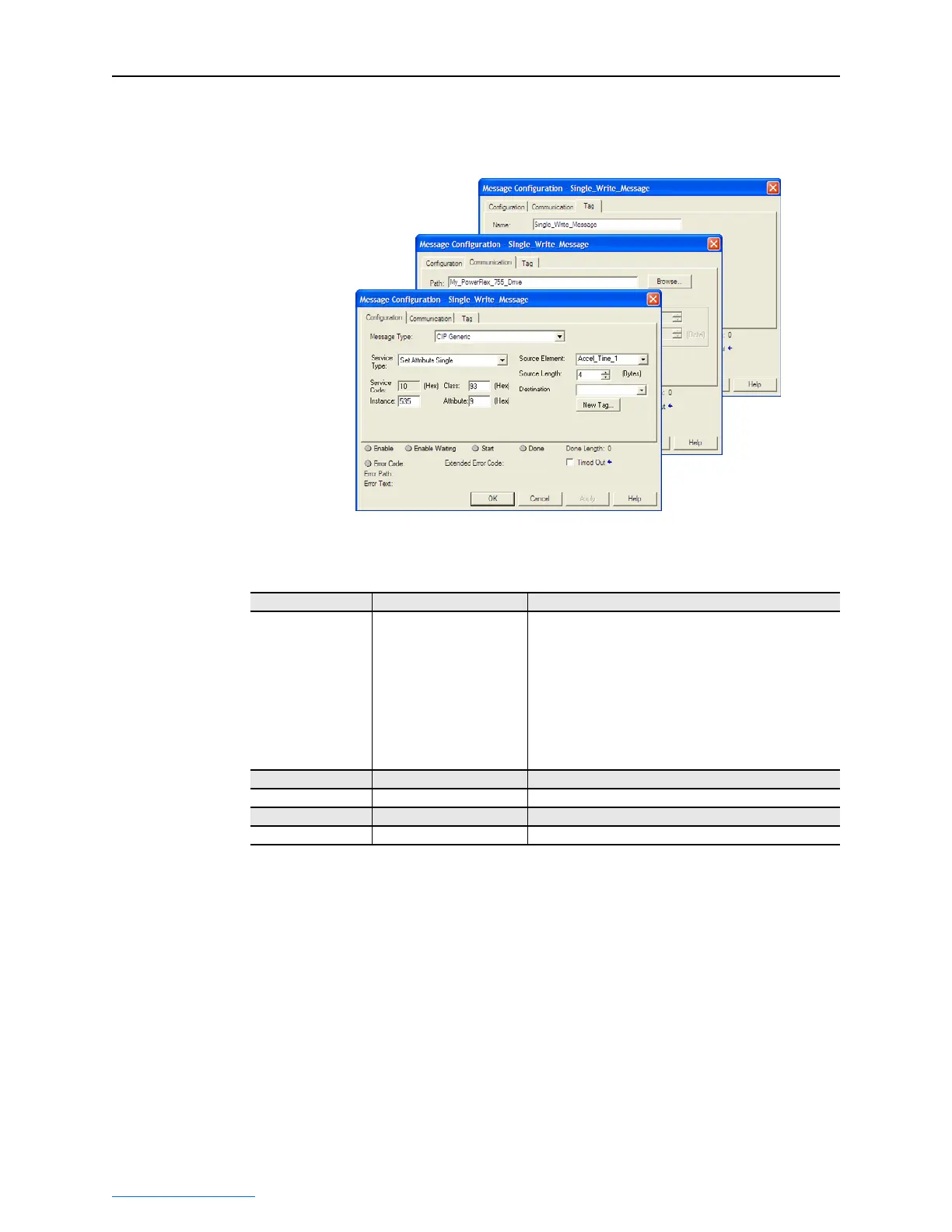
ControlLogix – Formatting a Message to Write Single Parameter
Figure 6.5 Set Attribute Single Message Configuration Screens
The following table identifies the data that is required in each box to
format a single write message.
Configuration Tab Example Value Description
Message Type
Service Type
(1)
Service Code
(1)
Class
Instance
Attribute
(2)
Source Element
Source Length
Destination
CIP Generic
Set Attribute Single
10 (Hex.)
93 (Hex.)
535 (Dec.)
9 or A (Hex.)
Accel_Time_1
(4)
4 bytes
(4)
—
Used to access the Parameter Object in the adapter.
This service is used to write a parameter value.
Code for the requested service.
Class ID for the DPI Parameter Object.
Instance number is the same as parameter number.
Attribute number for the Parameter Value attribute.
Name of the tag for any service data to be sent from the
scanner or bridge to the adapter/drive.
Number of bytes of service data to be sent in the message.
Leave blank (not applicable).
Communication Tab Example Value Description
Path
(3)
My_PowerFlex_755_Drive The path is the route that the message will follow.
Tag Tab Example Value Description
Name Single_Write_Message The name for the message.
(1)
The default setting for Service Type is “Custom,” enabling entry of a Service Code not available from the Service Type pull-down
menu. When selecting a Service Type other than “Custom” from the pull-down menu, an appropriate Hex. value is automatically
assigned to the Service Code box which grays out (unavailable).
(2)
Setting the Attribute value to “9” will write the parameter value to the drive’s Non-Volatile Storage (EEPROM) memory, so the
parameter value will remain even after the drive is power cycled. Important: When set to “9,” be very cautious as the EEPROM may
quickly exceed its life cycle and cause the drive to malfunction. Setting the Attribute value to “A” will write the parameter value to
temporary memory, so the parameter value will be lost after the drive is power cycled. It is recommended to use the “A” setting
when frequent write messages are required.
(3)
Click Browse to find the path, or type in the name of the device listed in the I/O Configuration folder (for this example,
My_PowerFlex_755_Drive).
(4)
In this example, Accel Time 1 is a 32-bit floating point parameter so the Data Type field must be set to “REAL” when creating the
controller tag. To write to a 32-bit DINT parameter, set the tag Data Type field to “DINT.” For a 16-bit parameter, set the Data
Type field to “INT.” Also, the Source Length field on the Message Configuration screen must correspond to the selected Data
Type in bytes (for example, 4 bytes for a REAL or DINT, or 2 bytes for an INT). Refer to the drive documentation to determine the
size of the parameter.

 Loading...