Configuring the I/O 4-39
PowerFlex® 755 Drive Embedded EtherNet/IP Adapter User Manual
Publication 750COM-UM001A-EN-P
message has to be executed first before the Logic Command, Reference,
and DL to Net Datalink messages will work. For more information on
N42:3 and N45 target device data table addresses, refer to N-Files
on
page C-8.
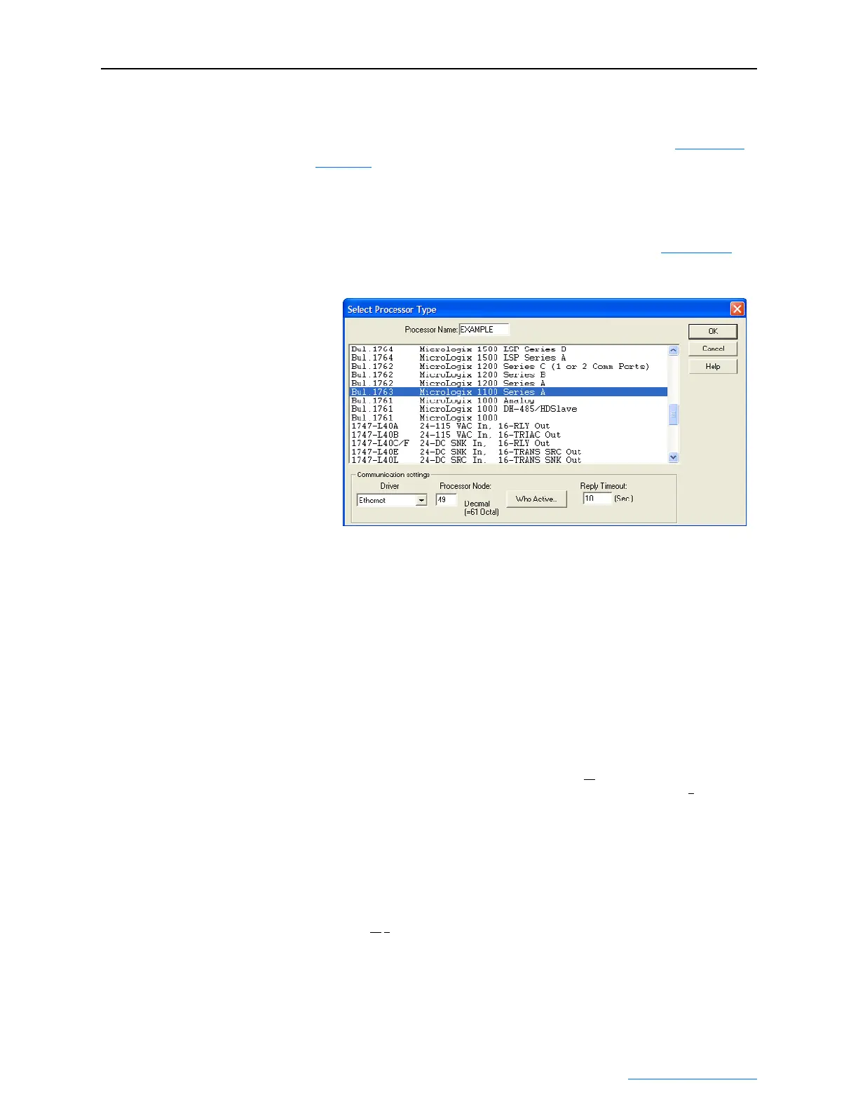
Selecting the Controller
1. Start RSLogix 500. The RSLogix 500 window appears. Select File
> New to display the Select Processor Type screen (Figure 4.42
).
Figure 4.42 MicroLogix 1100 Select Processor Type Screen
2. Assign a name for the processor. In the list, select the MicroLogix
1100. Then select the appropriate choices for the fields in the screen
to match your application, and click OK. The RSLogix 500 project
window appears.
Creating MicroLogix 1100 Ladder Logic for the Control Timeout
1. In the RSLogix 500 project window treeview under Program Files
double-click on LAD 2.
2. Insert a ladder rung, double-click on the rung to display the rung
editor, and enter MSG MGxx:n, where:
xx is an unused data file number (for example, MG10:n), and
n is an unused element of the data file chosen for xx (for example, MG10:0
)
Then press Enter.
3. Insert another separate rung, double-click on the rung to display the
rung editor, and enter BST XIC MGxx:n/DN NXB XIC MGxx:n/
ER BND OTU MGxx:n/EN, where:
xx and n must correspond to the assigned data file number and element (for example,
MG10
:0) for the message created in Step 2.
Important:The information must be entered with appropriate
numbers for “xx” and “n” for your application, and
with spaces and forward slashes exactly as shown.
Then press Enter.

 Loading...