Digital modules
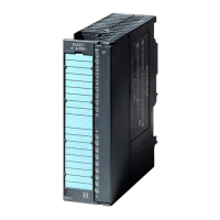
3.24 Digital output module SM 322; DO 16 x DC 24 V/0.5 A: (6ES7322-8BH10-0AB0)
S7-300 Module data
152 Manual, 06/2017, A5E00105505-AJ
Load resistances of the actuators
The load resistances of the actuators must be in the range from 48 Ω to 4 Ω. For larger
values, a suitable resistance must be switched directly on the connection clamps of the
actuator (observe the maximum power loss with signal "1").
The permissible rated voltage of the actuator must be greater than 28.2 V.
The lower response threshold of the actuator must be known in the operating temperature
range or be determined experimentally. The output voltage of the module with signal "0" can
be influenced through parallel switching of a resistance directly on the actuator connection
clamps. With the selection of the resistance, the maximum power loss with signal "1" must
be observed.
● Load resistances between 10 kΩ and 1 MΩ can be reported as short-circuits after L+.
● Unwired outputs or loads greater than 1 MΩ are reporeted as "wire-break".
3.24.1 Parameters of digital output modules
Programming
For general information on programming digital modules, refer to the chapter Programming
digital modules (Page 58).
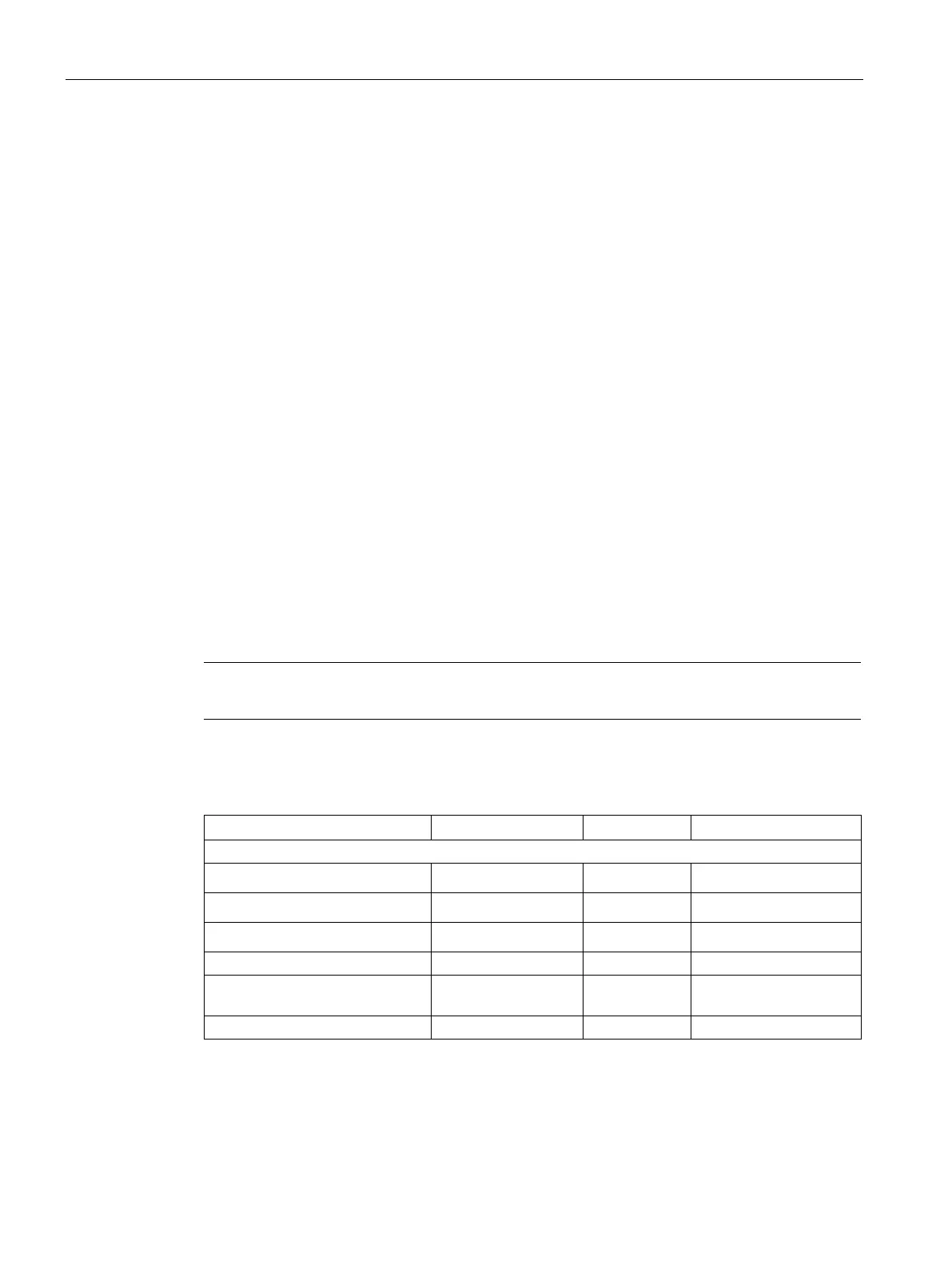
The table below describes the programmable parameters of SM 322; DO 16 x DC 24 V/0.5
A, including defaults.
Note
A setting of the module through SIMATIC PDM is not possible.
Table 3- 23 Setting for the digital output module SM 322; 6ES7322-8BH10-0AB0
• Group diagnostics
Yes/no no Channel
• Load voltage L+ missing
Yes/no No Channel group
• Discrepancy error
Yes/no No Channel group
Response at CPU-STOP Substitute a value/
Substitute a
Module
See also
Settings from the digital output module SM 322; DO 16 x DC 24 V/0.5 A
(6ES7322-8BH10-0AB0) (Page 530)

 Loading...