Analog modules
6.6 Analog input module SM 331; AI 8 x 13 Bit; (6ES7331-1KF02-0AB0)
S7-300 Module data
Manual, 06/2017, A5E00105505-AJ
339
6.5.4 Additional information on SM 331; AI 8 x 14 Bit High Speed, isochrone
Unused channels
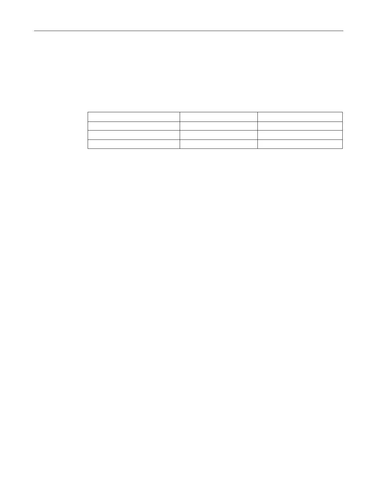
You should wire unused channels as shown in the following table. This optimizes
interference immunity of the analog input module.
Current / 4-wire transducer leave open connect with M-
Current / 2-wire transducer
As certain programmed inputs may remain unused due to the channel group configuration,
make allowances for the special features of these inputs outlined below in order to be able to
use the diagnostics functions at these used channels:
●
Measuring range 1 V to 5 V: wire the used input and unused input of the same channel
group in parallel.
● Current measurement, 2-wire transducer: There are two options of wiring the channel
circuit.
a) Open unused inputs; channel group diagnostics disabled. If you were to enable
diagnostics, the analog module would trigger a single diagnostic interrupt, and light up its
SF LED.
b) Loading the unused input using a 1.5 kΩ to 3.3 kΩ resistor. This allows you to enable
diagnostics for this channel group.
●
Current measurement 4 mA to 20 mA, 4-wire transducer: wire the used input and unused
input of the same channel group in series.
Line continuity check for the 4 mA to 20 mA measuring range
If you configured a measuring range of 4 mA to 20 mA, and enabled the line continuity
check, the analog input module logs a wire-break event to diagnostics data when the current
drops below 1.185 mA.
The module also triggers a diagnostics interrupt if this function is enabled in the program.
A wire break can only be signaled by means of the lit SF LED and the diagnostic bytes must
be evaluated in the user program if diagnostics interrupts are disabled.
If you configured a measuring range of 4 mA to 20 mA,
disabled the line continuity check,
and enabled diagnostic interrupts, the module triggers a diagnostic interrupt when the
underflow value is reached.

 Loading...