Parameter sets of signal modules
A.4 Parameters of digital output modules
S7-300 Module data
528 Manual, 06/2017, A5E00105505-AJ
A.4 Parameters of digital output modules
Parameter
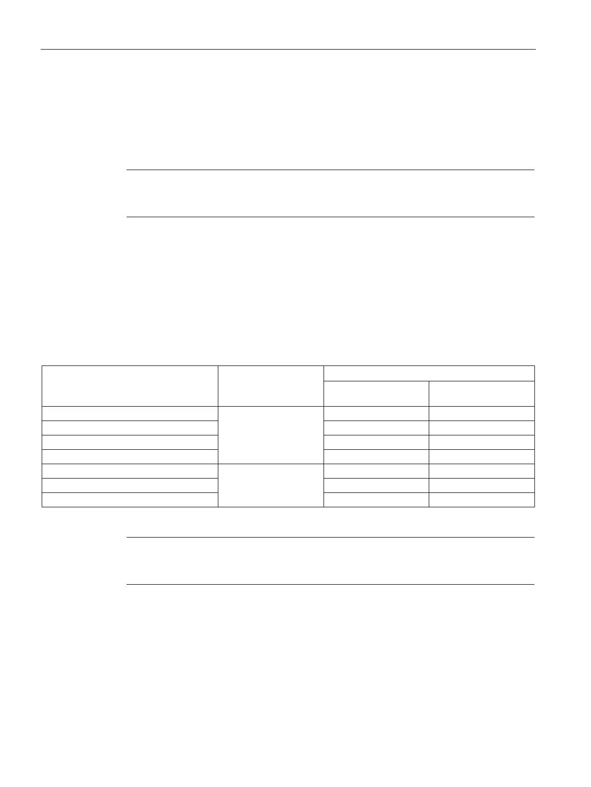
The table below contains all parameters you can set for digital output modules.
Note
For details on the parameters of pro
grammable digital IO modules, see the chapter dealing
with the relevant module.
The comparison illustrates the parameters you can edit:
● in
STEP 7
● using SFC55 "WR_PARM"
● using SFB53 "WRREC" (for GSD, for example).
Parameters set in
STEP 7
may also be transferred to the module using SFCs 56 and 57, and
SFB 53 (refer to the
STEP 7
) Online Help).
Table A- 4 Parameters of digital output modules
Diagnostics of missing load voltage L+
0
Diagnostics of short-circuit to M
Diagnosis of short-circuit to L+
Diagnostics interrupt enable
1
Note
To enable diagnostic interrupts in the user program at data record 1, you first need to enable
diagnostics at data record 0 in
STEP 7
.

 Loading...