Parameter sets of signal modules
A.3 Parameters of the digital input module SM 321; DI 16 x DC 24/125 V
S7-300 Module data
526 Manual, 06/2017, A5E00105505-AJ
A.3 Parameters of the digital input module SM 321; DI 16 x DC 24/125 V
Parameters
The table below lists the parameters you can set for digital input modules.
Note
For details on parameters of programmable digital IO modules, see the chapter dealing with
the relevant module.
The comparison illustrates the parameters you can edit:
● in
STEP 7
● using SFC55 "WR_PARM"
● using SFB53 "WRREC" (for GSD, for example).
Parameters set in
STEP 7
may also be transferred to the module using SFCs 56 and 57, and
SFB53 (refer to the
STEP 7
) Online Help).
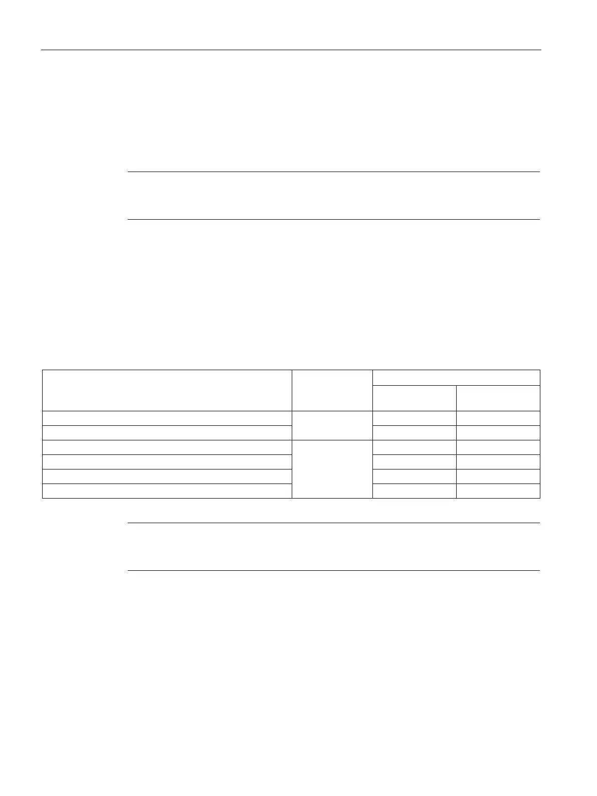
Table A- 3 Parameters of the digital input module SM 321; DI 16 x DC 24/125 V
0
Hardware interrupt enable
1
Diagnostic interrupt enable
Hardware interrupt at positive edge
Hardware interrupt at negative edge
Note
To enable diagnostic interrupts in the user program at data record 1, you first need to enable
diagnostics at d
ata record 0 in
STEP 7
.
Structure of data record 1
The figure below shows the structure of data record 1 for the parameters of digital input
modules.
You enable a parameter by setting a logical "1" at the corresponding bit.

 Loading...