Digital modules
3.26 Digital output module SM 322; DO 16 x UC 24/48 V; (6ES7322-5GH00-0AB0)
S7-300 Module data
Manual, 06/2017, A5E00105505-AJ
165
3.26.1 Parameters of digital output module SM 322 DO 16 x UC24/48 V
Programming
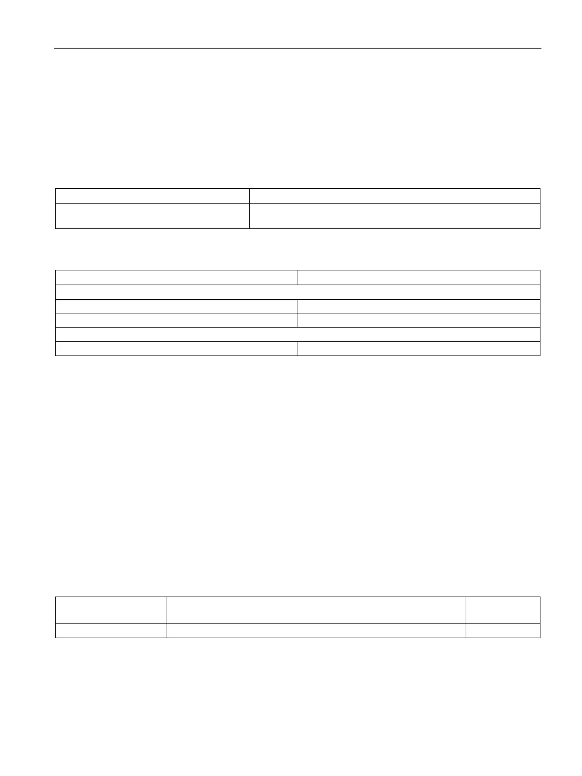
The tables below show data record numbers for static and dynamic parameters.
Table 3- 24 Data record 0 (static parameters):
Enable diagnostics Enabling an interrupt as a reaction to module failure caused by faulty
parameter, hardware error, or voltage error.
Table 3- 25 Data record 1 (dynamic parameters):
Each bit represents an output
This module supports fail state/substitution value outputs when the CPU changes from RUN
to STOP.
Status displays
Each output of this module is equipped with a green LED to indicate the relay state. In
addition, a red LED (SF) indicates the diagnostics status of the module.
Diagnostics, troubleshooting
Diagnostics data are assigned according to the technical data listed below.
The four system diagnostics data bytes can be read in the additional interrupt information as
data record 0, or in the first 4 bytes of data record 1.
Structure of the data record and system diagnostics for SM 322 DO 16x UC 24/48V
Structure of data record 1:
Table 3- 26 Structure of the data record for SM 322 DO 16 x UC 24/48 V
Data record 1 byte ad-
dress
System-specific diagnostics data

 Loading...