Principles of analog value processing
4.5 Wiring and connecting resistance thermometers and resistors
S7-300 Module data
Manual, 06/2017, A5E00105505-AJ
247
4.5 Wiring and connecting resistance thermometers and resistors
Introduction
This chapter describes the wiring and connecting of resistance thermometers and resistors
and rules to be observed.
Supported resistance transducers
● With 4-wire connection
● With 3-wire connection
● With 2-wire connection
Wiring and connecting resistance thermometers and resistors
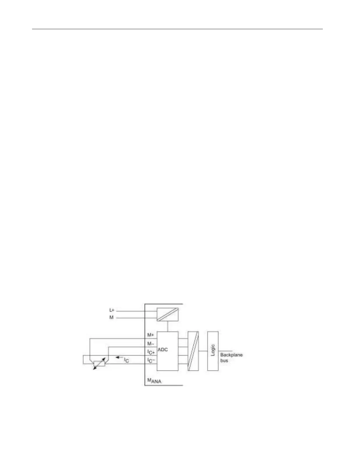
The module provides a constant current at terminals I
C+
and I
C-
for current measurements.
The constant current is fed to the resistance for measuring its voltage potential. The constant
current cables must be wired directly to the resistance thermometer/resistor.
Measurements programmed for 4-or 3-wire connections compensate for line resistance and
return considerably higher precision compared to 2-wire connections.
Measurements with programmed 2-wire connections also record line impedance in addition
to their internal resistance.
4-wire connection of a resistance thermometer
The voltage generated at the resistance thermometer is measured across the M
+
and M
-
terminals. Observe the correct polarity when wiring and connecting the devices (I
C+
and M
+
,
and I
C -
and M- at the resistance thermometer).
Always wire and connect the
I
C
+, M+, I
C
- and M- lines directly to the resistance
thermometer.
Figure 4-9 4-wire connection of resistance thermometers to an electrically isolated analog input

 Loading...