Analog modules
6.5 Analog input module SM 331; AI 8 x 14 Bit High Speed; isochrone; (6ES7331-7HF0x-0AB0)
S7-300 Module data
334 Manual, 06/2017, A5E00105505-AJ
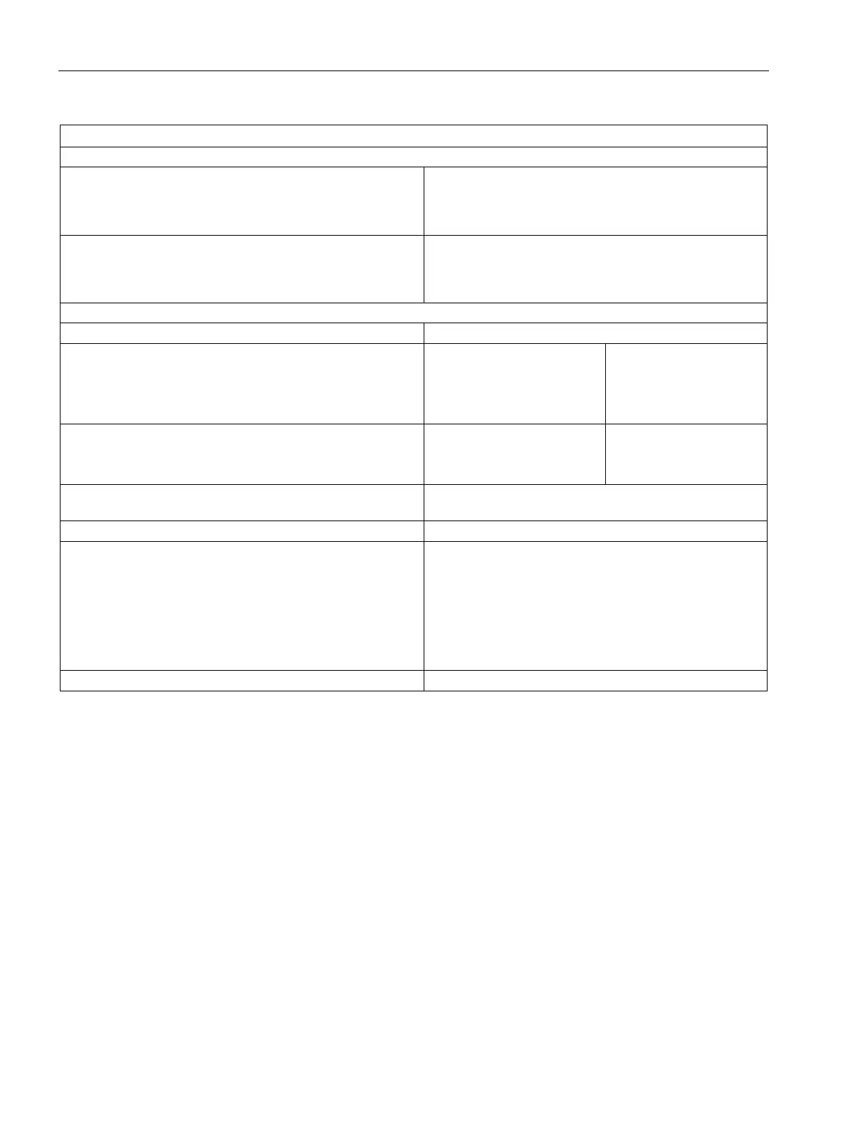
Status, interrupts, diagnostics
Interrupts
• Hardware interrupt
• Diagnostic interrupt
programmable
programmable
Diagnostic functions
• Group error display
• Reading diagnostics information
red LED (SF)
supported
Input ranges (rated values) / input impedance
• Voltage
± 1 V
± 5 V
± 10 V
10 MΩ
100 kΩ
100 kΩ
• Current
± 20 mA
0 mA to 20 mA
50 Ω
50 Ω
Maximum voltage at voltage input (destruction limit) max. 20 V continuous; 75 V for the duration of max. 1 s
Maximum current at current input (destruction limit)
Wiring of the signal transmitters
• for voltage measurement
• for current measurement
as 2-wire transducer
as 4-wire transducer
• Load of the 2-wire transducer at L+ = DC 24 V
using a 20-pin front connector
supported
supported
supported
max. 820 Ω
Characteristics linearization
6.5.1 Measurement types and measuring ranges
Introduction
The analog input module has measuring range modules. The measurement type and range
is configured at the "measuring range" parameter in
STEP 7
.
The default setting of the module
STEP 7
is "voltage" measurement with "± 10V" range. You
can use those default settings without having to program the SM 331;
AI 8 x 14 Bit High Speed in
STEP 7
.

 Loading...