Digital modules
3.11 Digital input module SM 321; DI 16 x 24 VDC; with hardware and diagnostic interrupts (6ES7321-7BH01-
0AB0)
S7-300 Module data
90 Manual, 06/2017, A5E00105505-AJ
3.11.4 SM 321; DI 16 x DC 24 V - Behavior
Influence of the operating state and supply voltage on input values
The SM 321; DI 16 x DC 24 input values are determined by the CPU's operating state and
the module's power supply.
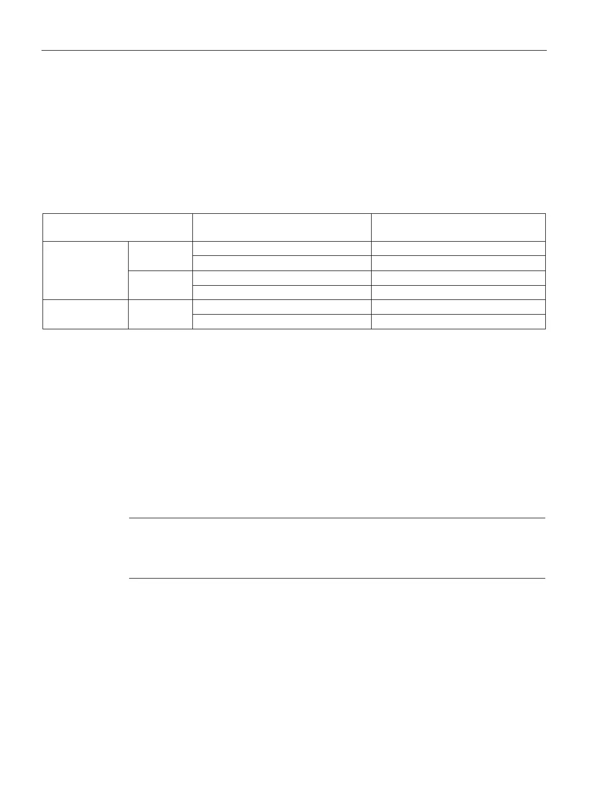
Table 3- 15 Dependency of input values on the CPU's operating state, and on the L+ power supply of
SM 321; DI 16 x DC 24 V
Power supply L+ at digital module
input value
of the digital module
POWER ON RUN
L+ missing 0 signal
STOP
L+ missing 0 signal
POWER OFF -
Reaction to power failure
Failure of the SM 321; DI 16 x DC 24 power supply is always indicated by the module's SF
LED. This information is also available on the module.
The input value is initially held for the duration of 20 ms to 40 ms before the zero signal is
transferred to the CPU. Supply voltage dips <20 ms do not influence the process value (see
the table above.)
Triggering of diagnostic interrupts is determined by the parameter settings (see chapter
Interrupts of SM 321; DO 16 x DC 24 V (Page 91)).
Power supply failure with redundant external sensor supply
Note
When an external redundant power source is connected in parallel to the sensor supply (Vs)
and the
L+ power supply fails, the module does not report failure of the sensor supply, but
rather the failure of the internal and/or external auxiliary voltage, and/or a blown fuse.
Short-circuit at the sensor supply Vs
The relevant Vs LED goes dark if a short-circuit is detected at the sensor supply Vs,
irrespective of parameter settings.

 Loading...