4-34 FI SYSTEM
“C13” IAP SENSOR CIRCUIT MALFUNCTION
INSPECTION
DETECTED CONDITION POSSIBLE CAUSE
Low pressure and low voltage.
High pressure and high voltage.
NOTE:
Note that atmospheric pressure caries depending
on weather conditions as well as altitude.
Take that into consideration when inspecting volt-
age.
• Clogged vacuum passage between throttle body
and IAP sensor.
• Air being drawn from vacuum passage between
throttle body and IAP sensor.
• Red wire circuit open or shorted to ground.
• B/Br or G/B wire circuit shorted to ground.
• IAP sensor malfunction.
• ECM malfunction.
()
0.10 V Sensor voltage
4.80 V
<
without the above range.
• Lift and support the fuel tank with its prop stay. (
:
4-51)
1
2
Ye s
Ye s
No
No
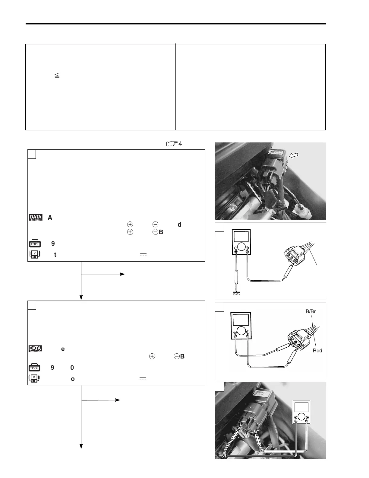
Turn the ignition switch OFF.
Check the IAP sensor coupler for loose or poor contacts.
If OK, then measure the IAP sensor input voltage.
Disconnect the IAP sensor coupler.
Turn the ignition switch ON.
Measure the voltage at the Red wire and ground.
If OK, then measure the voltage at the Red wire and B/Br
wire.
Connect the IAP sensor coupler.
Insert the copper wires to the lead wire coupler.
Start the engine at idling speed.
Measure the IAP sensor output voltage at the wire
side coupler (between G/B and B/Br wires).
;
IAP sensor input voltage: 4.5 – 5.5 V
z
09900-25008: Multi circuit tester
u
Tester knob indication: Voltage (
-
)
( )
Loose or poor contacts on
the ECM coupler.
Open or short circuit in
the Red wire or B/Br wire.
;
IAP sensor output voltage: Approx. 2.5 V at idle
speed (
+
G/B –
-
B/Br)
z
09900-25008: Multi circuit tester
u
Tester knob indication: Voltage (
-
)
Check the vacuum hose for
crack or damage.
Open or short circuit in the
G/B wire.
Replace the IAP sensor with
a new one.
V
G/B
G/B
B/BrB/Br
Red
1
1
2
+
Red –
-
Ground
+
Red –
-
B/Br
V
V

 Loading...


