EMISSION CONTROL INFORMATION 9-9
HEATED OXGEN SENSOR (HO
2
S) INSPECTION
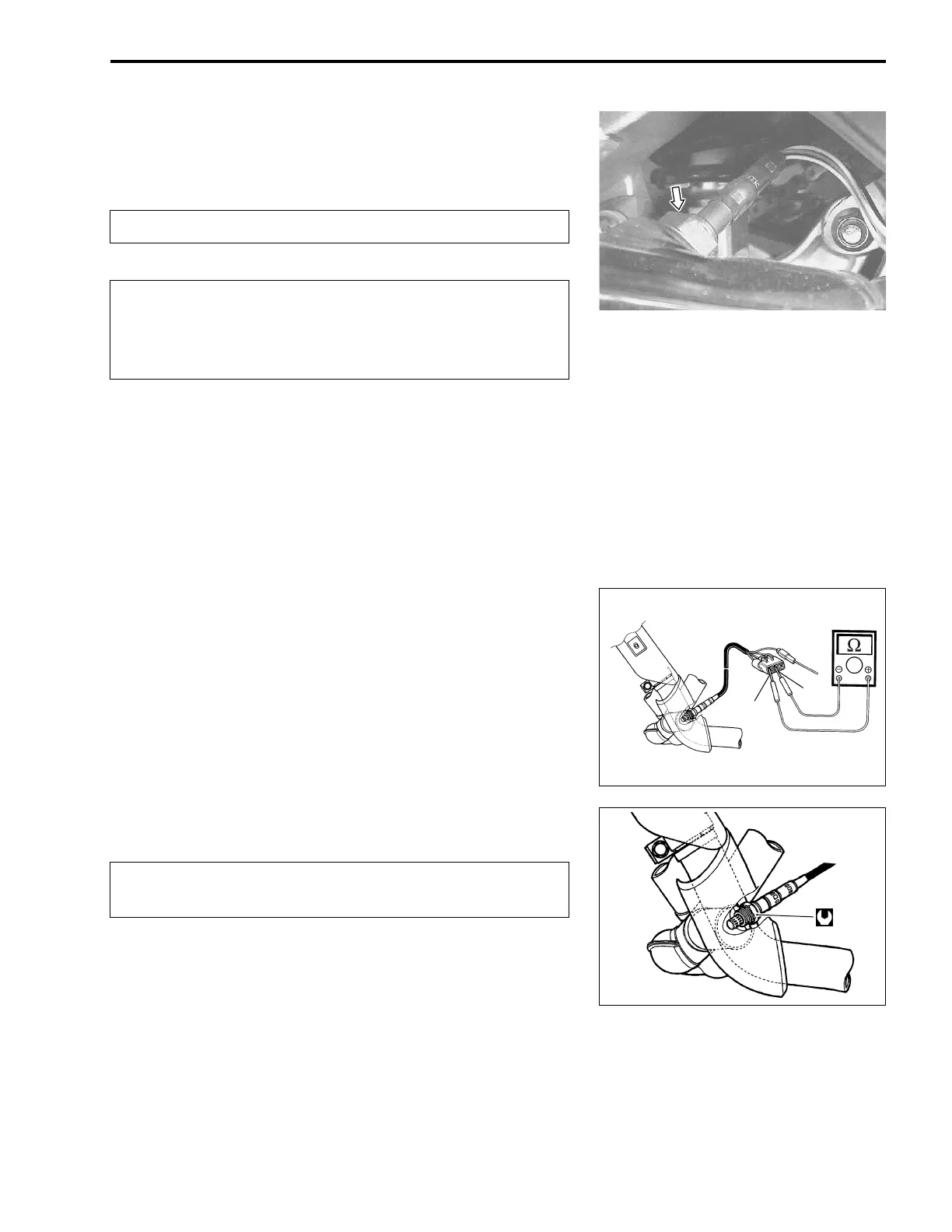
• Remove the engine under cover.
• Disconnect the HO
2 sensor lead wire coupler.
• Remove the HO
2
sensor unit.
%
#
• Inspect the HO
2
sensor and its circuit referring to flow table of
the malfunction code (C44).
• Disconnect the HO
2 sensor coupler.
• Check the resistance between the terminals of the HO
2
sen-
sor.
! Resistance: 4 – 5 Ω
ΩΩ
Ω (at 23 °C/73.4 °F)
" 09900-25008: Multi circuit tester set
$ Tester knob indication: Resistance (Ω
ΩΩ
Ω)
If the resistance is not within the standard range, replace the
HO
2 sensor with new one.
NOTE:
* Temperature of the sensor affects resistance value largely.
* Make sure that the sensor heater is at correct temperature.
• Connect the HO
2 sensor coupler securely.
• Installation is in the reverse order of removal.
#
• Tighten the sensor unit to the specified torque.
& HO2
SENSOR: 47.5 N·m (4.75 kgf-m, 34.3 lb-ft)
• Route the HO
2
sensor lead wire into the frame.
• Connect the HO
2
sensor coupler.
Do not remove the HO
2
sensor while it is hot.
Be careful not to expose it to excessive shock.
Do not use an impact wrench while removing or
installing the HO
2
sensor unit.
Be careful not to twist or damage the sensor lead wire.
White
White
Do not apply oil or other materials to the sensor air
hole.

 Loading...


