4-46 FI SYSTEM
“C31” GEAR POSITION (GP) SWITCH CIRCUIT MALFUNCTION
INSPECTION
DETECTED CONDITION POSSIBLE CAUSE
No Gear Position switch voltage
Switch voltage low.
• Gear Position switch circuit open or short.
• Gear Position switch malfunction.
• ECM malfunction.
( )
Switch Voltage > 1.0 V
without the above value.
• Lift and support the fuel tank with its prop stay. (
:
4-51)
1
Ye s
No
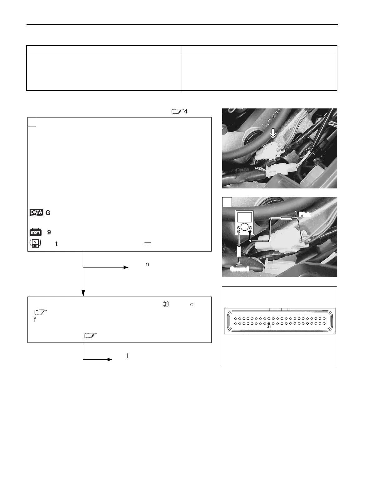
Turn the ignition switch OFF.
Check the GP switch coupler for loose or poor contacts.
If OK, then measure the GP switch voltage.
Support the motorcycle with a jack.
Turn the side-stand to up-right position.
Turn the engine stop switch ON.
Insert the copper wire to the lead wire coupler.
Turn the ignition switch ON.
Measure the voltage at the wire side coupler between
Pink wire and ground, when shifting the gearshift lever
from 1st to Top.
;
GP switch voltage: More than 1.0 V
(Pink – Ground)
z
09900-25008: Multi circuit tester
u
Tester knob indication: Voltage (
-
)
Open or short circuit in the
Pink wire.
Replace the GP switch
with a new one.
Pink wire open or shorted to ground, or poor
U
connection.
(
:
4-22)
If wire and connection are OK, intermittent trouble or faulty ECM.
Recheck each terminal and wire harness for open circuit and
poor connection. (
:
4-5)
Replace the ECM with a new one,
and inspect it again.
ECM coupler
V
Ground
Pink
1

 Loading...


