FI SYSTEM 4-69
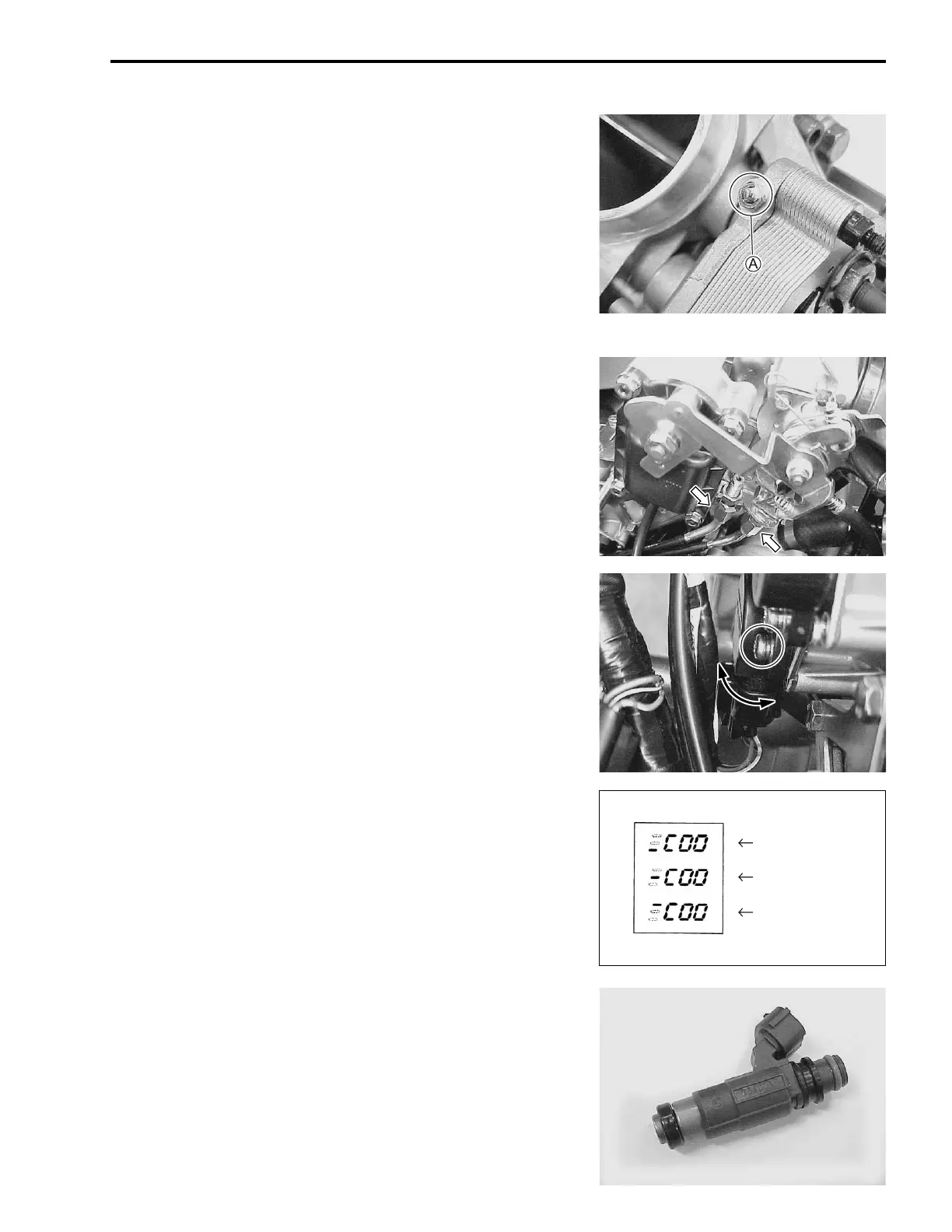
If the measured resistance is not within specification, adjust the
STV adjuster
A as follows:
• Under above condition, turn in or out the STV adjuster
A until
the resistance becomes specified value.
If the measured resistance is not obtain, replace the STP sen-
sor with a new one, and adjust the STP sensor positioning
again.
NOTE:
To adjust the TP sensor, install the throttle body assembly to the
engine and after warming up engine. (#4-64)
THROTTLE BODY INSTALLATION
Installation is in the reverse order of removal. Pay attention to
the following points:
• Connect the throttle pulling cable and throttle returning cable
to the throttle cable drum.
• Adjust the throttle cable play with the cable adjusters.
Refer to page 2-15 for details.
TP SENSOR ADJUSTMENT
• After checking or adjusting the throttle valve synchronization,
adjust the TP sensor positioning as follows:
• After warming up engine, adjust the idling speed to 1 200 ±
100 rpm.
• Stop the warmed-up engine and connect the special tool to
the dealer mode coupler. (#4-24)
! 09930-82710: Mode select switch
• If the TP sensor adjustment is necessary, loosen the TP sen-
sor mounting screws.
• Turn the TP sensor and bring the line to middle.
• Tighten the TP sensor mounting screws.
! 09930-11950: Torx wrench
' TP sensor mounting screw: 3.5 N·m (0.35 kgf-m, 2.5 lb-ft)
FUEL INJECTOR INSPECTION
The fuel injector can be checked without removing it from the
throttle body.
Refer to page 4-47 for details.
Incorrect
Correct position
Incorrect

 Loading...


