ENGINE 3-19
ENGINE DISASSEMBLY
ENGINE TOP SIDE
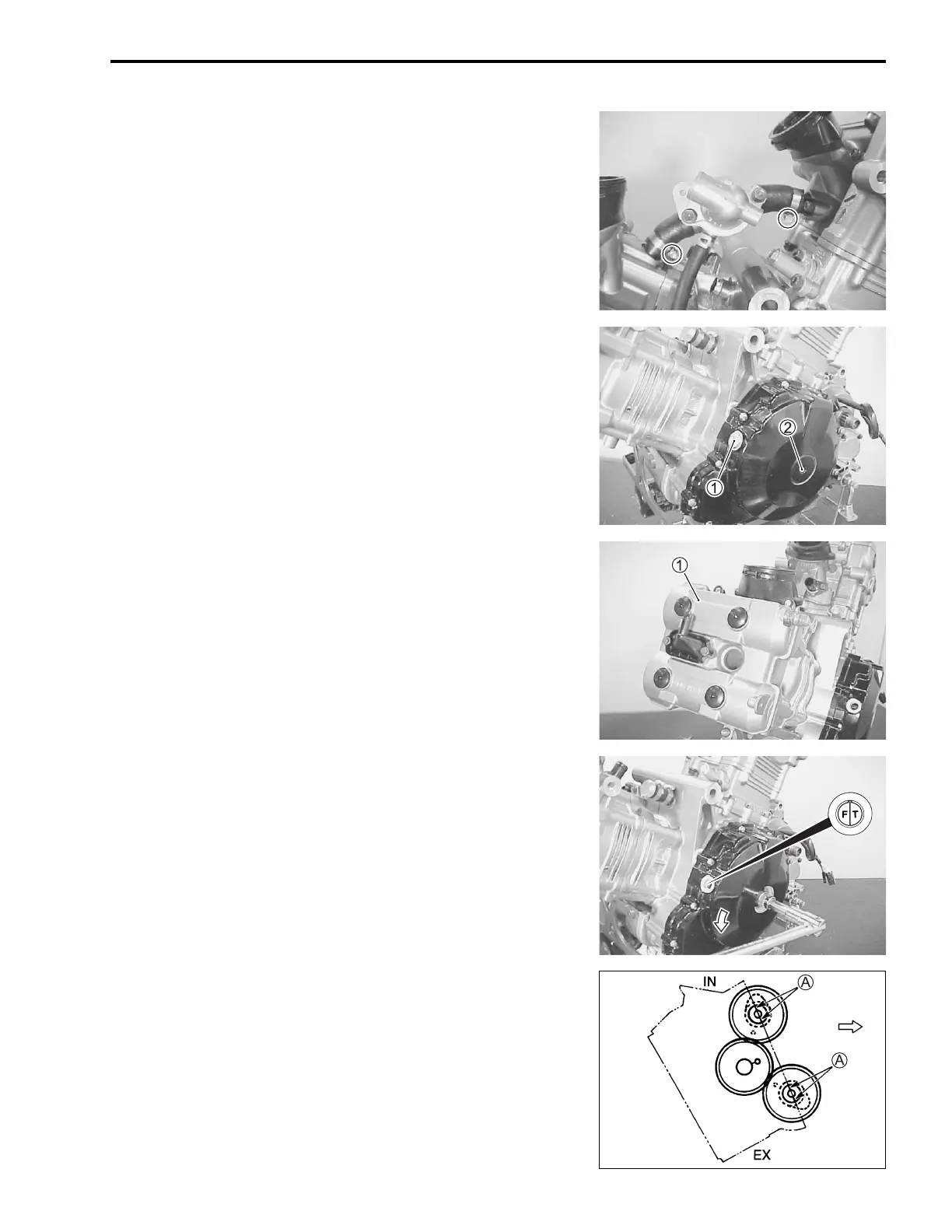
• Remove the thermostat.
• Remove the valve timing inspection plug
1 and generator
cover plug
2.
FRONT CYLINDER HEAD COVER
• Remove the front cylinder head cover
1.
• Turn the crankshaft to bring the “F | T” line on generator rotor
to the index mark of the valve inspection hole and also to
bring the cams to the position as shown.
NOTE:
At the above condition, the No.1 (Front) cylinder is at TDC of
compression stroke and also the engraved lines
A on the cam-
shafts are parallel with the mating surface of the cylinder head
cover.
FRONT
Front
cylinder head

 Loading...


