FI SYSTEM 4-75
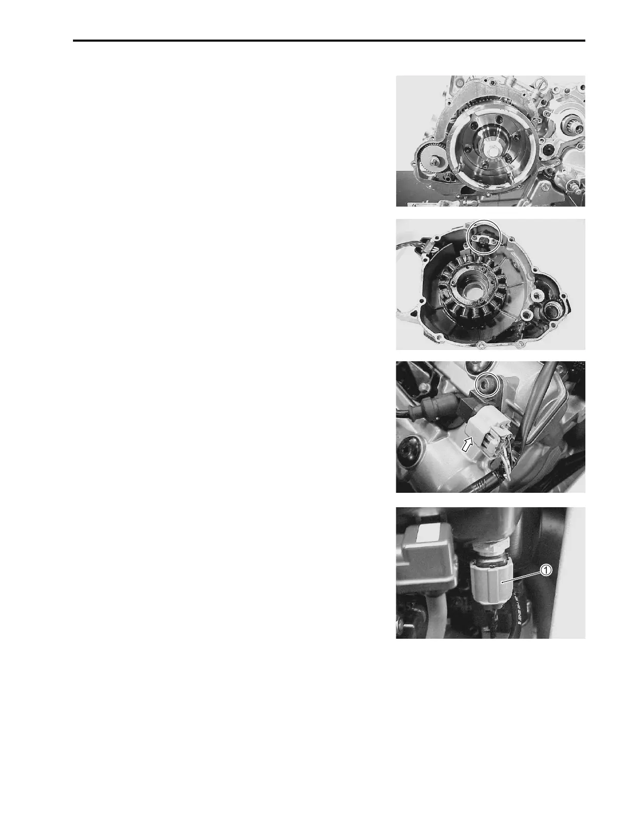
CKP SENSOR INSPECTION
The signal rotor is mounted on the generator rotor and crank-
shaft position sensor (Pick-up coil) is installed in the generator
cover. (#4-33)
CKP SENSOR REMOVAL/INSTALLATION
(#3-77)
CMP SENSOR INSPECTION
The signal rotor is installed on the No.2 intake camshaft, and the
camshaft position sensor (Pick-up coil) is installed on the No.2
cylinder head cover. (#4-32)
CMP SENSOR REMOVAL/INSTALLATION
• Lift and support the fuel tank. (#4-51)
• Disconnect the coupler and remove the CMP sensor.
Installation is in the reverse order of removal. (#3-34)
IAT SENSOR INSPECTION
The intake air temperature sensor is installed at the rear side of
the air cleaner box. (#4-39)
IAT SENSOR REMOVAL/INSTALLATION
• Lift and support the fuel tank. (#4-51)
• Disconnect the IAT sensor coupler
1 and remove the IAT
sensor from the air cleaner box.
• Installation is in the reverse order of removal.
' IAT sensor: 18 N·m (1.8 kgf-m, 13.0 lb-ft)

 Loading...


