7-14 ELECTRICAL SYSTEM
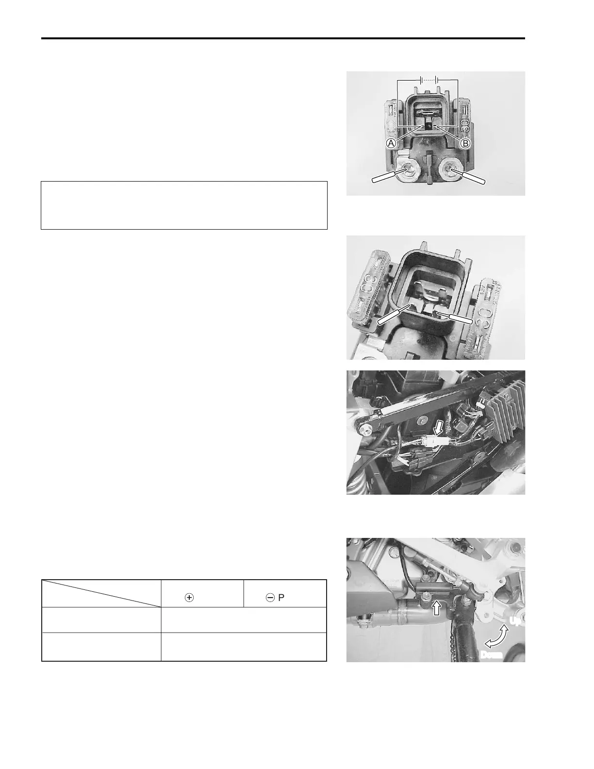
Apply 12 V to
A and
B terminals and check for continuity
between the positive and negative terminals using the multi cir-
cuit tester. If the starter relay clicks and continuity is found, the
relay is ok.
# 09900-25008: Multi circuit tester set
+ Tester knob indication: Continuity test (,
,,
,)
"
Measure the relay coil resistance between the terminals using
the multi circuit tester. If the resistance is not within the specified
value, replace the starter relay with a new one.
# 09900-25008: Multi circuit tester set
( Tester knob indication: Resistance (Ω
ΩΩ
Ω)
$ Starter relay resistance: 3 – 6 Ω
ΩΩ
Ω
SIDE-STAND/IGNITION INTERLOCK
SYSTEM PARTS INSPECTION
Check the interlock system for proper operation. If the interlock
system does not operate properly, check each component for
damage or abnormalities. If any abnormality is found, replace
the component with a new one.
SIDE-STAND SWITCH
• Remove the seat. (! 6-4)
• Remove the left frame cover. (!6-5)
• Disconnect the side-stand switch coupler and measure the
voltage between Green and Black/White lead wires.
# 09900-25008: Multi circuit tester set
) Tester knob indication: Diode test (*
**
*)
NOTE:
If the tester reads under 1.4 V when the tester probes are not
connected, replace its battery.
Do not apply a battery voltage to the starter relay for
more than five seconds, since the relay coil may over-
heat and damaged.
Up
Down
ON
(Side-stand up)
OFF
(Side-stand down)
Green
(
+
Probe)
Black/White
(
-
Probe)
0.4 – 0.6 V
More than 1.4 V
(Tester’s battery voltage)

 Loading...


