ELECTRICAL SYSTEM 7-15
GEAR POSITION SWITCH
• Remove the seat. (!6-4)
• Remove the fuel tank front cover.
• Remove the fuel tank side covers.
• Lift and support the fuel tank with the fuel tank prop stay.
(!4-51)
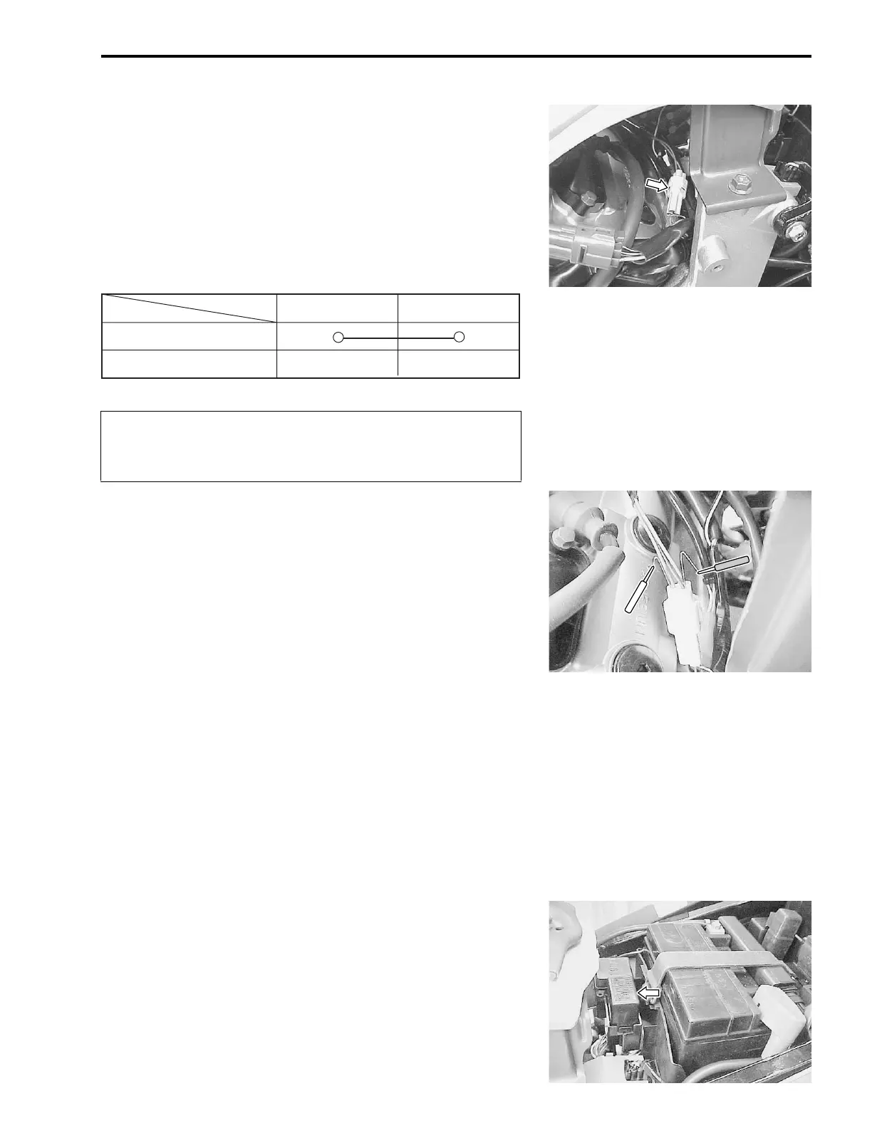
• Disconnect the gear position swtich coupler and check the
continuity between Blue and Black with the transmission in
“NEUTRAL”.
"
• Connect the gear position switch coupler to the wiring har-
ness.
• Turn the ignition switch to “ON” position and side-stand to
upright position.
Measure the voltage between Pink and Black lead wires using
the multi circuit tester when shifting the gearshift lever from low
to top.
# 09900-25008: Multi circuit tester set
' Tester knob indication: Voltage (&
&&
&)
$ Gear position switch voltage: More than 0.6V
NOTE:
* When connecting the multi circuit tester, use a fine copper wire
(O.D is below 0.5 mm) to the back side of the lead wire coupler
and connect the probes of tester to them.
* Use a fine copper wire, the outer diameter being below 0.5
mm, to prevent the rubber of the water proof coupler from
damage.
TURN SIGNAL/SIDE-STAND RELAY
The turn signal/side-stand relay is composed of the turn signal
relay, and the side-stand relay and diode.
• Remove the seat. (!6-4)
• Remove the turn signal/side-stand relay.
When disconnecting and connecting the gear position
switch coupler, make sure to turn OFF the ignition
switch, or electronic parts may get damaged.
ON (Neutral)
OFF (Expect neutral)
Blue
Black
(
* Low to top gear position
* Except neutral position
(
(Pink – Black)

 Loading...


