ELECTRICAL SYSTEM 7-21
• Shift the transmission into the neutral, and then turn the igni-
tion switch to the “ON” position.
• Pull the clutch lever.
• Press the starter button and allow the engine to crank for a
few seconds, and then measure the CKP sensor peak volt-
age.
• Repeat the above procedure a few times and measure the
highest peak voltage.
' Tester knob indication: Voltage (&
&&
&)
$ CKP sensor peak voltage: More than 3.7 V
If the peak voltage is lower than the specified values, check the
peak voltage at the CKP sensor lead wire coupler.
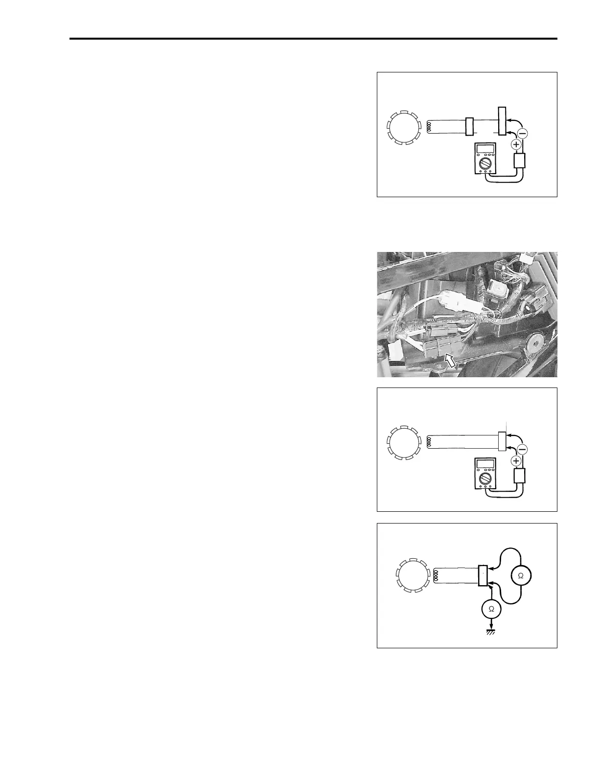
• Remove the left frame cover. (!6-5)
• Disconnect the CKP sensor lead wire coupler and connect the
multi circuit tester with the peak volt adaptor.
+ Probe: Green lead wire
- Probe: Blue lead wire
• Measure the CKP sensor peak voltage at the CKP sensor
lead wire coupler in the same manner as on the ECM coupler.
' Tester knob indication: Voltage (&
&&
&)
$ CKP sensor peak voltage: More than 3.7 V
If the peak voltage on the CKP sensor lead wire coupler is ok but
on the ECM coupler is out of specification, the wire harness
must be replaced. If both peak voltages are out of specification,
the CKP sensor must be replaced and re-checked.
CKP SENSOR RESISTANCE
Measure the resistance between the lead wires and ground. If
the resistance is not specified value, the CKP sensor must be
replaced.
# 09900-25008: Multi circuit tester set
( Tester knob indication: Resistance (Ω
ΩΩ
Ω)
$ CKP sensor resistance: 130 – 240 Ω
ΩΩ
Ω (Green – Blue)
∞
∞∞
∞ Ω
ΩΩ
Ω (Green – Ground)
CKP sensor
CKP sensor
coupler
G/W
W
ECM
coupler
Peak
volt
adaptor
W
Y/Bl
CKP sensor
Peak
volt
adaptor
CKP sensor
coupler
G
B
Bl
G
CKP sensor
CKP sensor
coupler

 Loading...


