7-32 ELECTRICAL SYSTEM
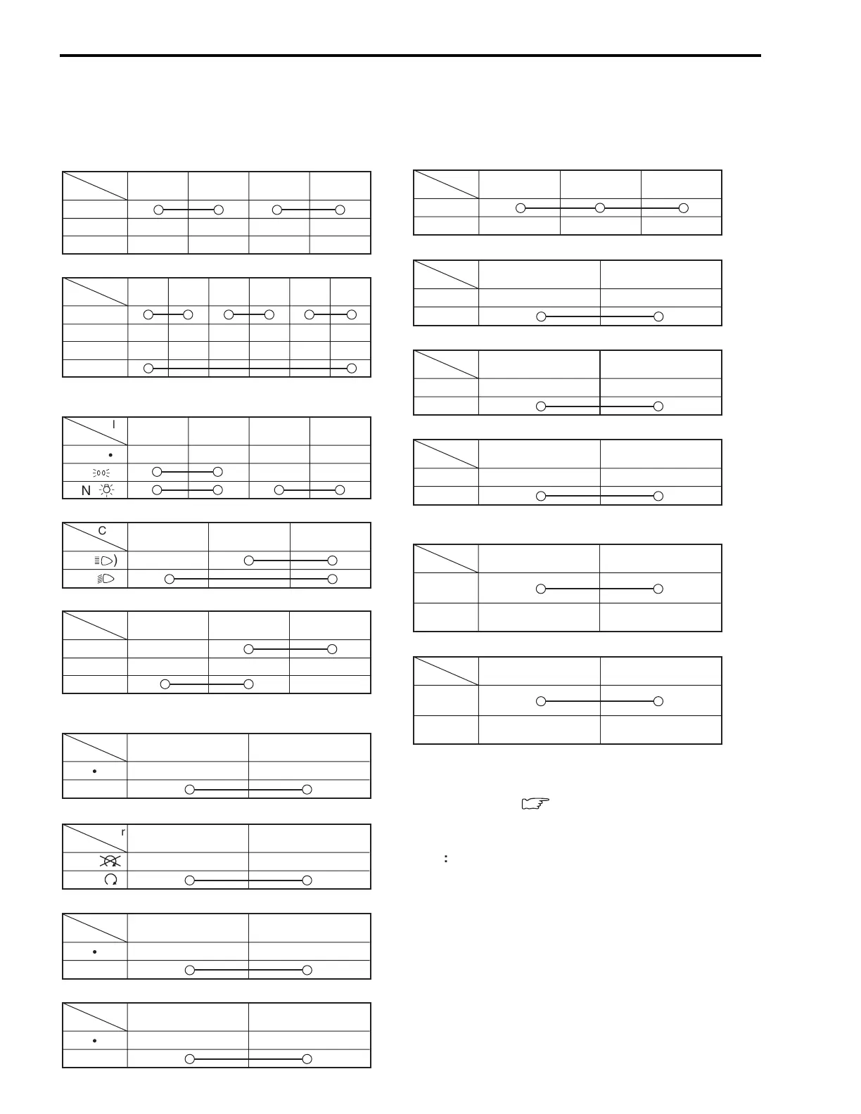
Inspect each switch for continuity with a tester. If any abnormality is found, replace the respective switch
assemblies with new ones.
G/Y Ground
ON (engine
is stopped)
OFF (engine
is running)
Color
Position
B Ground
ON (engine
is stopped)
OFF (engine
is running)
Color
Position
B/Y B/Y
OFF
ON
Color
Position
O/G W/B
OFF
ON
Color
Position
B/R B/Bl
OFF
ON
Color
Position
B/Bl B/W
PUSH
Color
Position
O/W Y/G
PUSH
Color
Position
ROO/YB/W
ON
OFF
LOCK
Color
Position
O/R Y
PUSH
Color
Position
Lg Lbl B
L
PUSH
R
Color
Position
WYY/W
HI
(
µ
)
LO
(
)
Color
Position
Lg Lbl B
ON
OFF
Color
Position
O/Bl Gr O/R Y/W
OFF
( )
S
(
½
)
ON
(
¼
)
Color
Position
R O O/Y B/W Gr Br
ON
OFF
LOCK
P
Color
Position
O/B O/W
OFF
(
À
)
RUN
(
¾
)
Color
Position
IGNITION SWITCH (For E24)
LIGHTING SWITCH
(Except for E03, E24, E28, E33)
HAZARD (Except for E03, E24, E28, E33)
OIL PRESSURE SWITCH
(For E03, E24, E28, E33)
PASSING LIGHT SWITCH
(Except for E03, E28, E33)
DIMMER SWITCH
HORN BUTTON
FRONT BRAKE SWITCH
REAR BRAKE SWITCH
CLUTCH LEVER POSITION SWITCH
ENGINE STOP SWICH
STARTER BUTTON
TURN SIGNAL SWITCH
(For Others)
(For Others)
NOTE:
Before inspecting the oil pressure switch, check the
engine oil level.(
:
2-13)
B : Black
Br : Brown
Gr : Gray
Lbl : Light blue
Lg : Light green
O : Orange
R : Red
Y : Yellow
W : White
Bl : Blue
G : Green
B/Bl : Black with Blue tracer
B/W : Black with White tracer
B/Y : Black with Yellow tracer
B/R : Black with Red tracer
G/Y : Green with Yellow tracer
O/B : Orange with Black tracer
O/Bl : Orange with Blue tracer
O/G : Orange with Green tracer
O/R : Orange with Red tracer
O/W : Orange with White tracer
O/Y : Orange with Yellow tracer
W/B : White with Black tracer
Y/G : Yellow with Green tracer
Y/W : Yellow with White tracer
WIRE COLOR

 Loading...


