1-63
Cisco ASA Series CLI Configuration Guide
Chapter 1 Configuring a Cluster of ASAs
Configuration Examples for ASA Clustering
port-channel span-cluster
nameif outside
ip address 209.165.201.1 255.255.255.224
ipv6 address 2001:DB8:2::8/64
mac-address 000C.F142.5CDE
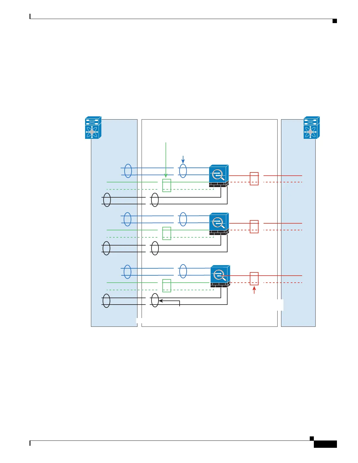
Redundant Interface (PBR or ECMP)
Redundant interfaces can be used to provide link-level redundancy.
When using Individual interfaces, switching to a backup interface is similar to how it behaves in
non-clustering mode. The ASA activates the backup link if the primary link fails. It takes time for the
Spanning Tree on the switch to converge before the backup link is activated on the switch side. The
backup links can be connected to a separate switch to provide inter-switch redundancy.
Interface Mode on Each Unit
cluster interface-mode individual force
ASA1 Master Bootstrap Configuration
interface tengigabitethernet 0/6
channel-group 1 mode on
ASA1
333220
ten0/6
ten0/7
ten1/6
man0/0
ten1/7
ten0/9
man0/1
ASA2
ten0/6
ten0/7
ten1/6
ten0/9
ASA3
ten0/6
ten0/7
ten1/6
ten0/8
ten0/8
ten0/8
ten0/9
Switch
port-ch1
port-ch4 port-ch5 port-ch6
port-ch2 port-ch3
Cluster Control Link
192.168.1.1, .2, and .3
inside
10.10.10.5/24 (Pool: .6-.9)
2001:DB8:4:3/64 (Pool: 4 IPs)
port-ch1port-ch1 port-ch1
port-ch2
Switch
man0/1
management
10.1.1.1 (Pool: .2-.5),
2001:DB8::1001/64 (Pool: 4 IPs)
man0/0
ten1/7
man0/1
man0/0
ten1/7
port-ch2 port-ch2
outside
209.165.201.1 (Pool: .2-.5)
2001:DB8:DD:1/64 (Pool: 4 IPs)
redund1 redund1 redund1
redund2redund2redund2
 Loading...