4.1.12.1.2 Assembling Power Cables
Assembling the OT Terminal and Power Cable
Background
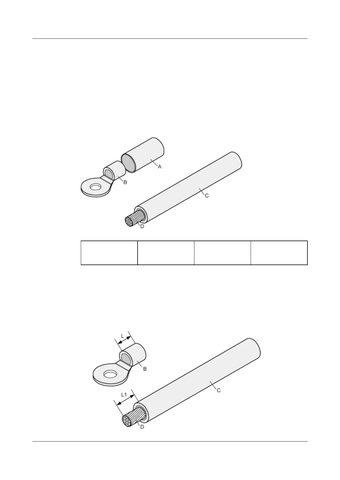
Figure 4-83 shows the components of an OT terminal and a power cable.
Figure 4-83 the components of an OT terminal and a power cable
A. Heat shrink
tubing
B. Bare crimping
terminal
C. Insulation D. Conductor
Procedure
1. Based on the cross-sectional area of the cable conductor, strip a length of
insulation coating C to expose the conductor D of length L1, as shown in
Figure 4-84. The recommended values of L1 are listed in Table 4-19.
Figure 4-84 Stripping a power cable (OT terminal)
HUAWEI NetEngine 8000 F
Hardware Guide 4 Hardware Installation and Parts Replacement
Issue 05 (2023-03-31) Copyright © Huawei Technologies Co., Ltd. 446
 Loading...