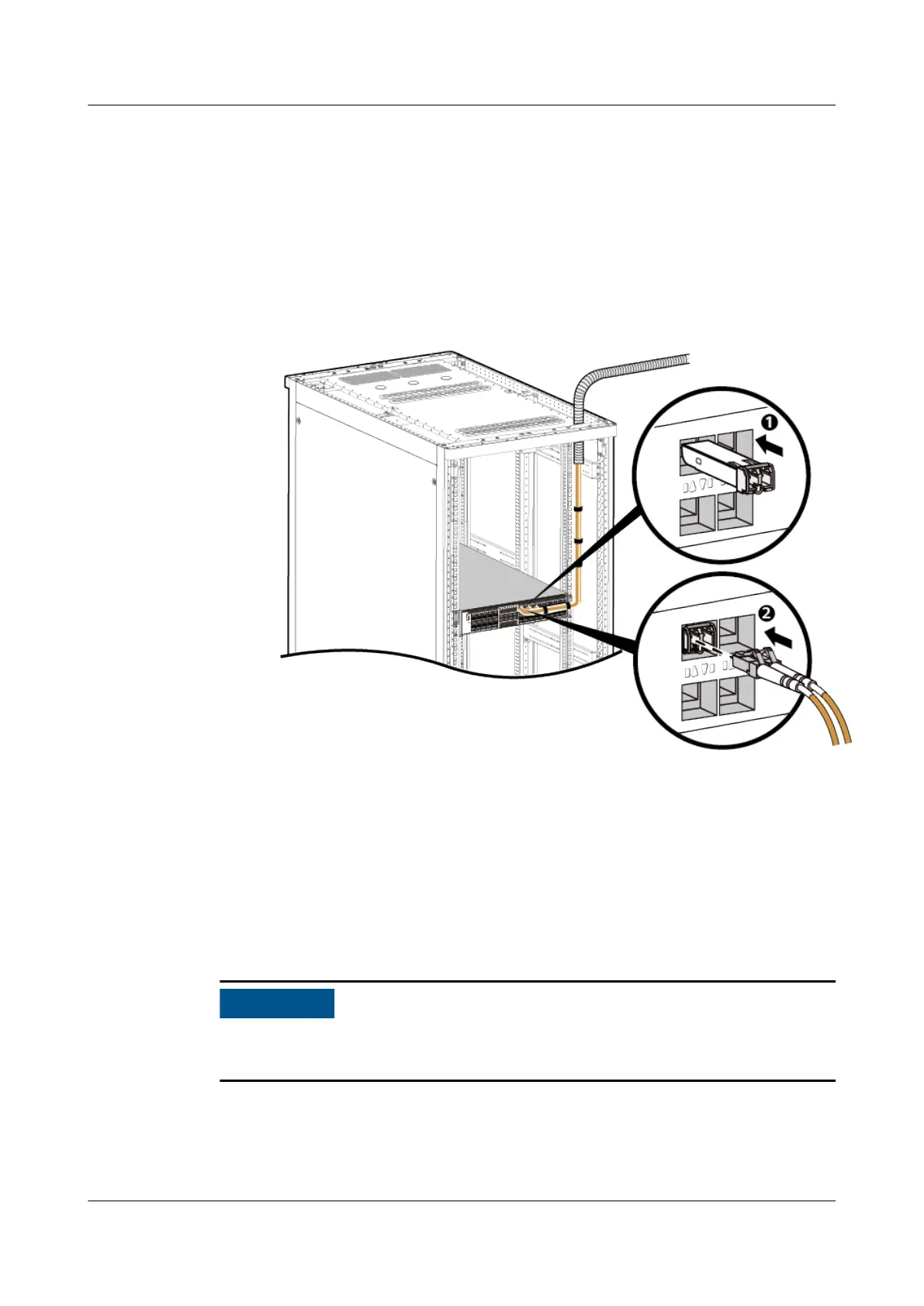
6. Install the optical module, as shown in step 1 in Figure 4-266.
7. Route optical bers along the cable tray, remove the dust caps from the
optical modules and optical ber interfaces. Then connect the end of each
optical ber to the corresponding optical interface, as shown in step 2 in
Figure 4-266.
Figure 4-266 Installing Optical Fibers
8. Connect the other end of each optical ber to the ODF.
9. Bundle optical bers with binding straps at an interval of 150 mm and fasten
the optical
bers to the cable tray.
10. Attach permanent labels 20 mm from both ends of each optical ber.
4.2.7.2 Installing Network Cables
Before bundling network cables, use a network cable tester to test cable
connectivity.
HUAWEI NetEngine 8000 F
Hardware Guide 4 Hardware Installation and Parts Replacement
Issue 05 (2023-03-31) Copyright © Huawei Technologies Co., Ltd. 613
 Loading...