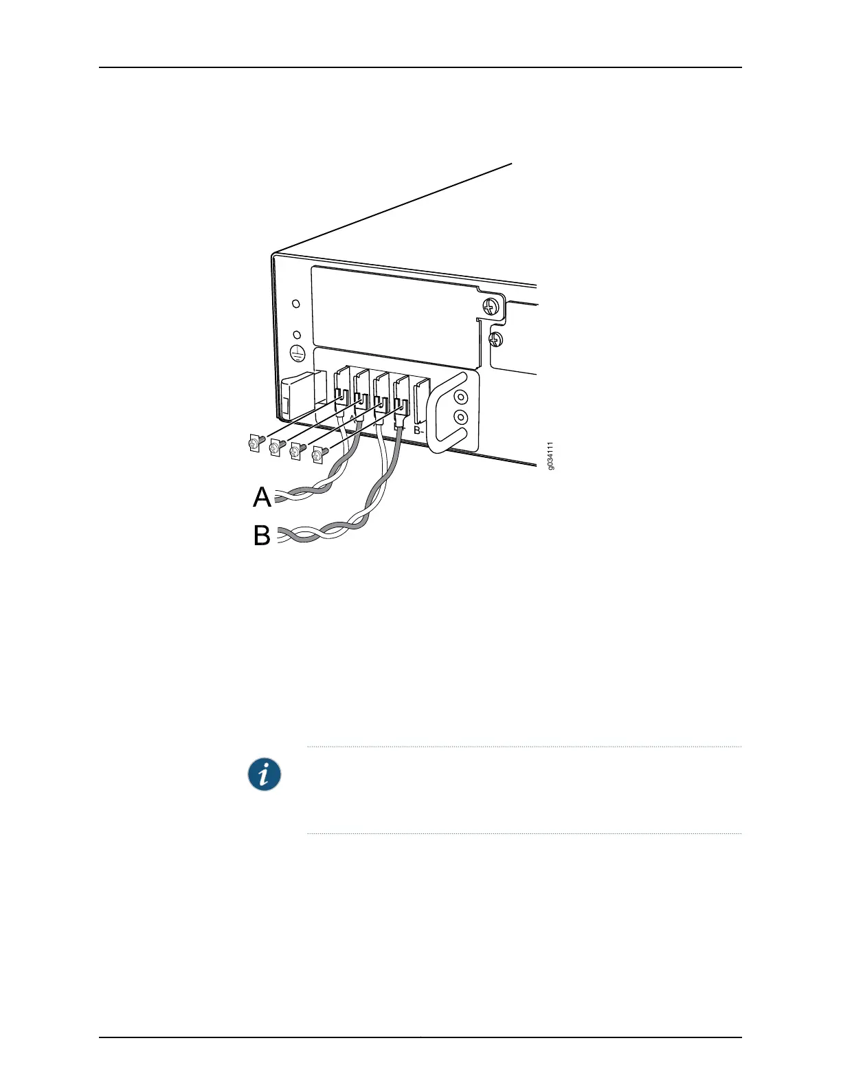
Figure 22: Connecting DC Power Cables
9. Replace the clear plastic cover over the terminal studs on the faceplate.
10. Verify that the power cables are connected correctly, that they are not touching or
blocking access to services gateway components, and that they do not drape where
people could trip on them.
11. Remove the tape from the switch handle of the circuit breaker on the panel board
that services the DC circuit and switch the circuit breaker to the on position ( | ).
Observe the status LEDs on the power supply faceplate. If the power supply is correctly
installed and functioning normally, the POWER LED lights green steadily on the services
gateway front panel.
NOTE: If more than one power supply is installed, turn on all power supplies
at the same time. If both power supplies are plugged in and receiving power,
the RPS LED glows solid green.
Related
Documentation
• Preventing Electrostatic Discharge Damage to the SRX550 High Memory Services
Gateway on page 194
• Required Tools and Parts for Replacing Hardware Components on the SRX550 High
Memory Services Gateway on page 159
• Removing a DC Power Supply from the SRX550 High Memory Services Gateway on
page 166
Copyright © 2016, Juniper Networks, Inc.102
SRX550 High Memory Services Gateway Hardware Guide
 Loading...