feed. This configuration provides the commonly deployed A/B feed redundancy for the
system. Table 24 on page 43 describes the connection terminals on the DC power supply.
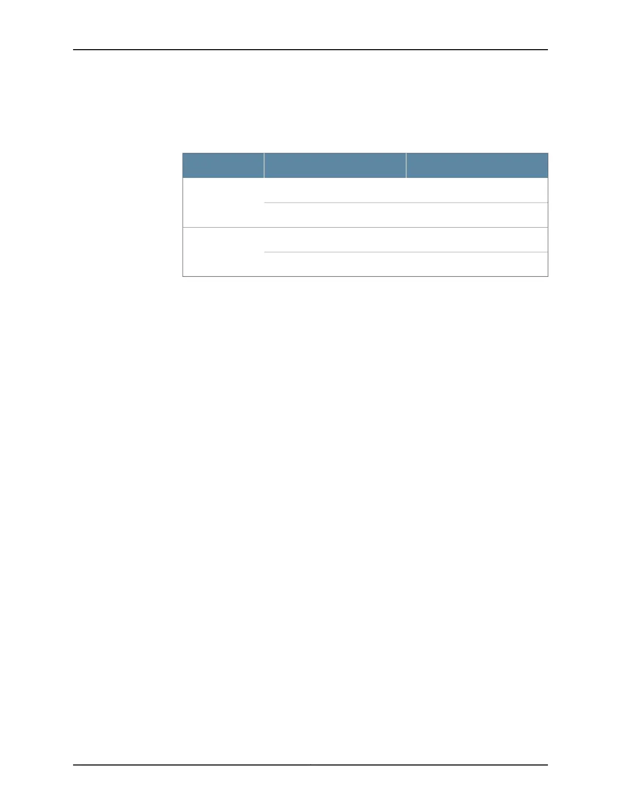
Table 24: DC Power Supply Terminals
DescriptionLabelFeed
RTN connection for Feed AA+Feed A
-48VDC connection for Feed AA-
RTN connection for Feed BB+Feed B
-48VDC connection for Feed BB-
Related
Documentation
• SRX550 High Memory Services Gateway Chassis on page 13
• SRX550 High Memory Services Gateway Front Panel on page 14
• SRX550 High Memory Services Gateway Back Panel on page 19
• SRX550 High Memory Services Gateway Cooling System on page 39
• Troubleshooting the Power System on the SRX550 High Memory Services Gateway
on page 150
43Copyright © 2016, Juniper Networks, Inc.
Chapter 5: Power System Description
 Loading...