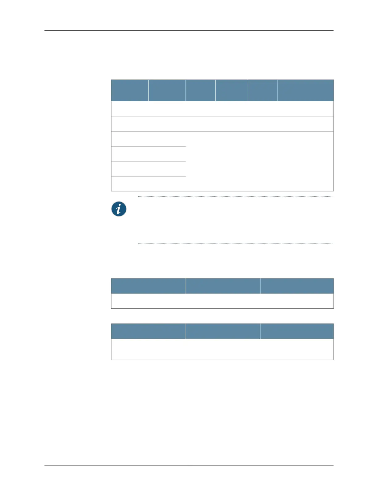
Table 53: Default Interface Configuration for the Services
Gateway (continued)
Address
DHCP
State
Security
ZoneConnectorInterfacePort Label
192.168.4.1/24ServerTrustRJ-45ge-0/0/40/4
192.168.5.1/24ServerTrustRJ-45ge-0/0/50/5
No default configurationge-0/0/60/6
ge-0/0/70/7
ge-0/0/80/8
ge-0/0/90/9
NOTE: If chassis clustering is enabled, we recommend using the port labeled
0/0 port as the management port (fxp0) and using the 0/1 port (if used) as
the control port (fxp1). The fxp0 and fxp1 ports are created only when chassis
clustering is enabled. You can use the other ports as fabric ports.
By default, the security policies and NAT rules in Table 54 on page 126 and
Table 55 on page 126 are created on the SRX Series security policies.
Table 54: Security Policies
Policy ActionDestination ZoneSource Zone
PermitUntrustTrust
Table 55: NAT Rule
NAT ActionDestination ZoneSource Zone
Source NAT to untrust zone
interface
UntrustTrust
For example, a common default firewall configuration includes the following assumptions:
•
The protected network is connected to the interfaces ge-0/0/1 (port 0/1) through
interface ge-0/0/5 (port 0/5) in the trust zone.
•
Connectivity to the Internet is through the interface ge-0/0/0 (port 0/0) in the untrust
zone.
•
The IP address of the ge-0/0/0 interface is assigned through DHCP.
Copyright © 2016, Juniper Networks, Inc.126
SRX550 High Memory Services Gateway Hardware Guide
 Loading...