Home
Juniper
Gateway
SRX550
Juniper SRX550 Hardware Guide
5
of 1
of 1 rating
246 pages
Give review
Manual
Specs
To Next Page
To Next Page
To Previous Page
To Previous Page
Loading...
P
ART
1
Ov
erview
•
S
yst
em
Overview
on
page
3
•
Chassis
Description
on
page
13
•
Interf
ace
Module
Description
on
page
23
•
Cooling
Syst
em
Description
on
page
39
•
P
ow
er
Sy
stem
Description
on
page
41
1
Cop
yright
©
2016,
Juniper
Network
s,
Inc.
22
24
Table of Contents
Table of Contents
3
About the Documentation
17
Documentation and Release Notes
17
Supported Platforms
17
Documentation Conventions
17
Table 1: Notice Icons
18
Table 2: Text and Syntax Conventions
18
Documentation Feedback
19
About the Documentation
19
Requesting Technical Support
20
Self-Help Online Tools and Resources
20
Opening a Case with JTAC
20
Overview
23
Chassis Description
23
System Overview
23
Interface Module Description
23
Power System Description
23
System Overview
25
Chapter 1 System Overview
25
System Overview
25
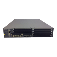
SRX550 High Memory Services Gateway Description
25
Figure 1: SRX550 High Memory Services Gateway
25
SRX550 High Memory Services Gateway Description
26
SRX550 High Memory Services Gateway Hardware Features
26
SRX550 High Memory Services Gateway Software Features and Licenses
26
System Overview
27
Table 3: Software Features and Licenses
27
SRX550 High Memory Services Gateway Power over Ethernet
30
Table 4: SRX550 High Memory Services Gateway Poe Specifications
31
Accessing the SRX550 High Memory Services Gateway
32
Scheme
32
Figure
32
Documentation
32
Chassis Description
35
SRX550 High Memory Services Gateway Chassis
35
Table 5: Physical Specifications for the SRX550 High Memory Services
35
Chapter 2 Chassis Description
35
Figure 2: SRX550 High Memory Services Gateway Front Panel
36
SRX550 High Memory Services Gateway Front Panel
36
Table 6: SRX550 High Memory Services Gateway Front Panel Components
36
Figure 3: SRX550 High Memory Services Gateway Slot Numbers
39
Figure 4: SRX550 High Memory Services Gateway Front Panel LED
39
SRX550 High Memory Services Gateway Front Panel Leds
39
Table 7: SRX550 High Memory Services Gateway Front Panel Leds
40
Figure 5: SRX550 High Memory Services Gateway Back Panel
41
SRX550 High Memory Services Gateway Back Panel
41
Table 8: SRX550 High Memory Services Gateway Back Panel Components
42
Interface Module Description
45
Chapter 3 Interface Module Description
45
SRX550 High Memory Services Gateway Gigabit-Backplane Physical Interface Modules Overview
45
Figure 6: SRX550 High Memory Services Gateway Slot Numbers
46
Figure 7: Example of a Standard GPIM (Installs in One Standard Slot)
46
Figure 8: Example of a Double-High, Single-Wide XPIM
46
8-Port Gigabit Ethernet SFP XPIM
47
Interface Module Description
47
Figure 9: 8-Port Gigabit Ethernet SFP XPIM Front Panel
47
8-Port Gigabit Ethernet SFP XPIM Components
48
8-Port Gigabit Ethernet SFP XPIM Hardware Specifications
48
8-Port Gigabit Ethernet SFP XPIM Leds
48
Table 9: 8-Port Gigabit Ethernet SFP XPIM Components
48
Table 10: 8-Port Gigabit Ethernet SFP XPIM Physical Specifications
48
8-Port Gigabit Ethernet SFP XPIM Supported Transceivers
49
Table 11: 8-Port Gigabit Ethernet SFP XPIM LED States
49
Table 12: 8-Port Gigabit Ethernet SFP XPIM Supported Modules
49
8-Port Gigabit Ethernet SFP XPIM Network Interface Specifications
50
Table 13: 8-Port Gigabit Ethernet SFP XPIM Network Interface Specifications
50
16-Port Gigabit Ethernet XPIM (Poe)
51
Figure 10: 16-Port Gigabit Ethernet with Poe XPIM
51
16-Port Gigabit Ethernet XPIM (Poe) Components
52
16-Port Gigabit Ethernet XPIM (Poe) Hardware Specifications
52
Table 14: 16-Port Gigabit Ethernet XPIM Components
52
Table 15: 16-Port Gigabit Ethernet XPIM Hardware Specifications
52
16-Port Gigabit Ethernet XPIM (Poe) Leds
53
SRX550 High Memory Services Gateway Mini-Physical Interface Modules Overview
53
Table 16: 16-Port Gigabit Ethernet XPIM LED States
53
Overview
54
1-Port Serial Mini-Physical (SRX-MP-1SERIAL-R) Interface Module
54
Figure 11: 1-Port Serial Mini-PIM (SRX-MP-1SERIAL-R) Front Panel
54
1-Port Serial Mini-Physical Interface Module (SRX-MP-1SERIAL-R) Hardware Specifications
55
1-Port Serial Mini-Physical Interface Module (SRX-MP-1SERIAL-R) Leds
55
1-Port Serial Mini-Physical Interface Module Interface Cables
55
Table 17: 1-Port Serial Mini-PIM (SRX-MP-1SERIAL-R) Physical
55
Table 18: 1-Port Serial Mini-PIM (SRX-MP-1SERIAL-R) LED States
55
Table 19: Juniper Networks Serial Cables
55
1-Port T1/E1 Mini-Physical (SRX-MP-1T1E1-R) Interface Module
56
Figure
56
1-Port T1/E1 Mini-Physical Interface Module (SRX-MP-1T1E1-R) Hardware Specifications
57
1-Port T1/E1 Mini-Physical Interface Module (SRX-MP-1T1E1-R) Leds
57
Table 20: 1-Port T1/E1 Mini-PIM (SRX-MP-1T1E1-R) Physical Specifications
57
1-Port T1/E1 Mini-Physical Interface Module (SRX-MP-1T1E1-R) Supported Loopback Diagnostics
58
Table 21: 1-Port T1/E1 Mini-PIM (SRX-MP-1T1E1-R) LED States
58
1-Port T1/E1 Mini-Physical Interface Module (SRX-MP-1T1E1-R) Network Interface Specifications
59
Table 22: 1-Port T1/E1 Mini-PIM (SRX-MP-1T1E1-R) Network Interface
59
Chapter 4 Cooling System Description
61
SRX550 High Memory Services Gateway Cooling System
61
Chapter 5 Power System Description
63
SRX550 High Memory Services Gateway Power Supply
63
Figure 13: AC Power Supply
63
Figure 14: DC Power Supply
64
Table 23: Component Power Output/Consumption
64
Table 24: DC Power Supply Terminals
65
Chapter 6 Planning and Preparing the Site
67
Power Requirements and Specifications
67
Site Planning and Specifications
67
Planning and Preparing the Site
69
Site Preparation Checklist for the SRX550 High Memory Services Gateway
69
General Site Installation Guidelines for the SRX550 High Memory Services
69
Table 25: Site Preparation Checklist for SRX550 High Memory Services Gateway
69
Gateway
71
SRX550 High Memory Services Gateway Environmental Specifications
72
Table 26: SRX550 High Memory Services Gateway Environmental
72
Rack Requirements
75
Rack-Mounting Requirements and Warnings
75
SRX550 High Memory Services Gateway Rack Size and Strength
75
Chapter 7 Rack Requirements
75
Rack Requirements
77
Requirements
79
Flange Holes
79
Clearance Requirements for Airflow and Hardware Maintenance of the SRX550 High Memory Services Gateway
80
Figure 15: Airflow through the Chassis
80
Table 27: Clearance Requirements for the SRX550 High Memory Services
81
Cabinet Requirements
83
SRX550 High Memory Services Gateway Cabinet Size and Clearance
83
Requirements
83
SRX550 High Memory Services Gateway Cabinet Airflow Requirements
84
Chapter 8 Cabinet Requirements
83
Chapter 9 Power Requirements and Specifications
85
SRX550 High Memory Services Gateway Electrical Wiring Guidelines
85
Table 28: Site Electrical Wiring Guidelines for the SRX550 High Memory Services Gateway
85
SRX550 High Memory Services Gateway Supported AC Power Cords
86
Figure 16: AC Plug Types
87
Table 29: AC Power Cord Specifications
87
Specifications
88
SRX550 High Memory Services Gateway DC Power Cable Specifications
88
Table 30: AC Power Supply Electrical Specifications for the SRX550 High Memory Services Gateway
88
Specifications
89
Table 31: DC Power Cable Specifications
89
Table 32: DC Power Supply Electrical Specifications for the SRX550 High Memory Services Gateway
89
Cable Specifications and Pinouts
91
Chapter 10 Cable Specifications and Pinouts
91
Interface Cabling and Wiring Specifications for the SRX550 High Memory Services Gateway
91
Connector Pinouts for the SRX550 High Memory Services Gateway Ethernet Port
92
Ethernet Port
92
Table 33: Cable and Wire Specifications for Ports and Alarm Interfaces
92
Table 34: RJ-45 Connector Pinouts for Services Gateway Ethernet Port
92
Connector Pinouts for the SRX550 High Memory Services Gateway Console Port
93
Console Port
93
Table 35: RJ-45 Connector Pinouts for the Services Gateway Console Port
93
Module
94
Table 36: EIA-530A DCE Cable Pinouts for the 1-Port Serial Mini-PIM
94
EIA-530A DCE Cable Pinouts for the 1-Port Serial Mini-Physical Interface Module
94
Module
95
Table 37: EIA-530A DTE Cable Pinouts for the 1-Port Serial Mini-PIM
95
EIA-530A DTE Cable Pinouts for the 1-Port Serial Mini-Physical Interface Module
95
Module
96
RS-232 DCE Cable Pinouts for the 1-Port Serial Mini-Physical Interface Module
96
Module
97
Table 38: RS-232 DCE Cable Pinouts for the 1-Port Serial Mini-PIM
97
RS-232 DTE Cable Pinouts for the 1-Port Serial Mini-Physical Interface Module
97
Interface Module
98
Table 39: RS-232 DTE Cable Pinouts for the 1-Port Serial Mini-PIM
98
RS-422/449 (EIA-449) DCE Cable Pinouts for the 1-Port Serial Mini-Physical Interface Module
98
Table 40: RS-422/449 DCE Cable Pinouts for the 1-Port Serial Mini-PIM
99
Interface Module
100
Table 41: RS-422/449 DTE Cable Pinouts for the 1-Port Serial Mini-PIM
100
RS-422/449 (EIA-449) DTE Cable Pinouts for the 1-Port Serial Mini-Physical Interface Module
100
DCE Cable Pinouts for the 1-Port Serial Mini-Physical Interface Module
102
Table 42: V.35 DCE Cable Pinouts for the 1-Port Serial Mini-PIM
102
DTE Cable Pinouts for the 1-Port Serial Mini-Physical Interface Module
103
Table 43: V.35 DTE Cable Pinouts for the 1-Port Serial Mini-PIM
103
X.21 DCE Cable Pinouts for the 1-Port Serial Mini-Physical Interface Module
104
Table 44: X.21 DCE Cable Pinouts for the 1-Port Serial Mini-PIM
104
DTE Cable Pinouts for the 1-Port Serial Mini-Physical Interface Module
104
DTE Cable Pinouts for the 1-Port Serial Mini-Physical Interface Module
105
Table 45: X.21 DTE Cable Pinouts for the 1-Port Serial Mini-PIM
105
Initial Installation and Configuration
107
Installation
107
Installation Overview
109
Chapter 11 Installation Overview
109
Installation Overview
109
Installation Overview for the SRX550 High Memory Services Gateway
109
Gateway
110
Installation Instructions Warning
110
Required Tools and Parts for Installing the SRX550 High Memory Services Gateway
110
SRX550 High Memory Services Gateway Autoinstallation Overview
111
Chapter 12 Unpacking the SRX550 High Memory Services Gateway
113
Chapter 13 Installing the Mounting Hardware
117
Preparing the SRX550 High Memory Services Gateway for Rack-Mount
117
Installation
117
Connecting the SRX550 High Memory Services Gateway to the Building
117
Structure
117
Preparing the SRX550 High Memory Services Gateway for Rack-Mount Installation
117
Chapter 14 Installing the SRX550 High Memory Services Gateway
119
Installing the SRX550 High Memory Services Gateway in a Rack
119
Figure 17: Installing the Rack Mount Brackets (Front Mount Position)
119
Figure 18: Installing the Rack Mount Brackets (Center Mount Position)
120
Figure 19: Installing the Services Gateway in the Rack
120
Services Gateway" on Page
113
Verifying Parts Received with the SRX550 High Memory Services Gateway
114
Table 46: Parts List for a Fully Configured SRX550 High Memory Services
114
Table 47: Accessory/Upgrade Parts List for the SRX550 High Memory Services
115
Chapter 15 Gateway
121
Figure 20: Installing an AC Power Supply on the SRX550 High Memory Services
121
Installing a DC Power Supply on the SRX550 High Memory Services
122
Gateway
122
Figure 21: Installing a DC Power Supply on an SRX550 High Memory Services
122
Figure 22: Connecting DC Power Cables
124
Grounding the SRX550 High Memory Services Gateway
127
SRX550 High Memory Services Gateway Grounding Specifications
127
Table 48: Grounding Cable Specifications for the SRX550 High Memory Services
127
Grounding the SRX550 High Memory Services Gateway
128
Chapter 16 Connectingthesrx550Highmemoryservicesgatewaytoexternal
131
Devices
131
Organizing Interface Cables on the SRX550 High Memory Services Gateway
131
Connecting the Modem to the Console Port on the SRX550 High Memory Services Gateway
132
Connecting to the SRX550 High Memory Services Gateway from the CLI with the USB Console Port
132
Figure 23: Console Cable Connector
132
Figure 24: Connecting to the USB Console Port on the SRX550 High Memory
133
Connecting the CLI at the User End for the SRX550 High Memory Services Gateway
134
Table 49: Port Settings
134
Configuring the Modem at the SRX550 High Memory Services Gateway End
135
Table 50: Port Settings
135
Table 51: Port Settings
136
Chapter 17 Providing Power to the SRX550 High Memory Services Gateway
137
Source
137
Figure 25: Connecting an AC Power Cord
138
Figure 26: Connecting DC Power Cables
141
Powering on the SRX550 High Memory Services Gateway
142
Powering off the SRX550 High Memory Services Gateway
142
Chapter 18 Performing Initial Configuration
145
SRX550 High Memory Services Gateway Basic Connectivity Overview
145
Built-In Ethernet Ports for the SRX550 High Memory Services Gateway
146
Table 52: Services Gateway Prerequisite Tasks
146
Table 53: Default Interface Configuration for the Services Gateway
147
Table 54: Security Policies
148
Table 55: NAT Rule
148
Management Access for the SRX550 High Memory Services Gateway
149
Viewing Factory-Default Settings of the SRX550 High Memory Services
150
Gateway
150
SRX550 High Memory Services Gateway Secure Web Access Overview
150
Configuring the SRX550 High Memory Services Gateway Using J-Web
151
Configuring Root Authentication
151
Connect the Management Device to the Ethernet Port
152
Figure 27: Connecting to the Ethernet Port on the SRX550 High Memory Services
152
Table 56: Factory-Default Settings-Interfaces
152
Verify the Settings
153
Locally
153
Figure 28: Connecting to the Console Port on the SRX550 High Memory Services
154
Table 57: Port Settings
154
Remotely
155
Configuring the SRX550 High Memory Services Gateway Using the CLI
156
Configuring Gigabit-Backplane Physical Interface Modules
158
Configuring Mini-Physical Interface Modules
159
Using the J-Web Interface
159
Using the CLI
160
Maintaining and Troubleshooting Components
163
Maintaining Components
165
Required Tools and Parts for Maintaining the SRX550 High Memory Services Gateway Hardware Components
165
Routine Maintenance Procedures for the SRX550 High Memory Services
165
Gateway
165
Maintaining the SRX550 High Memory Services Gateway Cooling System
165
Components
165
Maintaining the SRX550 High Memory Services Gateway Power Supply
166
Chapter 19 Maintaining Components
165
Troubleshooting Components
167
Gateway
167
Chapter 20 Troubleshooting Components
167
Table 58: Component Leds on the Services Gateway Chassis
168
Troubleshooting with Leds on the SRX550 High Memory Services Gateway
168
Troubleshooting with Chassis and Interface Alarm Messages on the SRX550
169
Table 59: Alarms for Services Gateway Chassis Components
170
Troubleshooting with Chassis and Interface Alarm Messages on the SRX550 High Memory Services Gateway
170
Troubleshooting the Power System on the SRX550 High Memory Services
171
Gateway
172
Table 60: POWER LED Description
172
Table 61: Power Supply Faceplate Leds
174
Gateway
175
Changing the RESET CONFIG Button Behavior on the SRX550 High Memory Services Gateway
176
Resetting the SRX550 High Memory Services Gateway
176
Juniper Networks Technical Assistance Center
177
Replacing Components
179
Part 5 Replacing Components
179
Overview of Replacing Components
181
Required Tools and Parts for Replacing Hardware Components on the SRX550 High Memory Services Gateway
181
Table 62: Tools and Parts Required for Replacing Services Gateway Hardware
181
Chapter 21 Overview of Replacing Components
181
Chapter 22 Replacing Power System Components
183
Gateway
183
Gateway
184
Gateway
185
Figure 29: Removing an AC Power Supply from the SRX550 High Memory
185
Figure 30: Installing an AC Power Supply on the SRX550 High Memory Services
186
Figure 31: Connecting an AC Power Cord on the SRX550 High Memory Services
186
Gateway
187
Removing a DC Power Supply Cable from the SRX550 High Memory Services Gateway
187
Removing a DC Power Supply from the SRX550 High Memory Services
187
Gateway
188
Gateway
189
Figure 32: Removing a DC Power Supply from the SRX550 High Memory Services
189
Figure 33: Installing a DC Power Supply on an SRX550 High Memory Services
190
Figure 34: Connecting DC Power Cables
191
Chapter 23 Replacing Mini-Physical Interface Modules
193
Gateway
193
Removing a Mini-Physical Interface Module
193
Installing a Mini-Physical Interface Module
194
Removing a Blank Mini-Physical Interface Module Faceplate
195
Installing a Blank Mini-Physical Interface Module Faceplate
195
Chapter 24 Replacing Gigabit-Backplane Physical Interface Modules
197
Replacing Gigabit-Backplane Physical Interface Modules on the SRX550 High Memory Services Gateway
197
Removing a Gigabit-Backplane Physical Interface Module
197
Table 63: LED Indications for Hot-Swappable GPIM Components
197
Installing a Gigabit-Backplane Physical Interface Module
198
Faceplate
199
Table 64: Hot-Swappable Component Descriptions for Gpims
199
Faceplate
200
Chapter 25 Contacting Customer Support and Returning Components
201
Contacting Customer Support
201
Return Procedure for the SRX550 High Memory Services Gateway
202
Locating the SRX550 High Memory Services Gateway Chassis Serial Number
203
And Agency Label
203
Number Labels
203
With the CLI
203
Information You Might Need to Supply to JTAC
204
Gateway
205
Packing the SRX550 High Memory Services Gateway for Shipment
205
Packing SRX550 High Memory Services Gateway Components for Shipment
206
Chapter 26 Safety
209
Part 6 Safety
209
General Safety Guidelines and Warnings
211
SRX550 High Memory Services Gateway Definition of Safety Warning Levels
211
SRX550 High Memory Services Gateway General Safety Guidelines and Warnings
211
Warnings
213
SRX550 High Memory Services Gateway Safety Requirements, Warnings, and Guidelines
214
Restricted Access Area Warning
214
Preventing Electrostatic Discharge Damage to the SRX550 High Memory Services
216
Gateway
216
Figure 35: Placing a Component into an Electrostatic Bag
216
Fire Safety Requirements
217
SRX550 High Memory Services Gateway Fire Safety Requirements and Fire Suppression Equipment
217
Laser and LED Safety Guidelines and Warnings
219
General Laser Safety Guidelines
219
Class 1 Laser Product Warning
220
Class 1 LED Product Warning
220
Laser Beam Warning
221
Radiation from Open Port Apertures Warning
222
Maintenance and Operational Safety Guidelines and Warnings
225
Battery Handling Warning
225
Lightning Activity Warning
226
Jewelry Removal Warning
227
Operating Temperature Warning
229
Product Disposal Warning
230
Electrical Safety Guidelines and Warnings
233
In Case of Electrical Accident
233
General Electrical Safety Guidelines and Warnings
233
AC Power Electrical Safety Guidelines and Warnings
234
DC Power Electrical Safety Guidelines and Warnings
235
Agency Approvals and Regulatory Compliance Information
243
SRX550 High Memory Services Gateway Agency Approvals
243
SRX550 High Memory Services Gateway Acoustic Noise Compliance
243
Statements
243
SRX550 High Memory Services Gateway Compliance Statements for EMC Requirements
244
Canada
245
European Community
245
Israel
245
Japan
245
United States
245
Lithium Battery
246
Other manuals for Juniper SRX550
Quick Start Guide
14 pages
Manual
10 pages
Setup Guide
6 pages
Quick Start
4 pages
5
Based on 1 rating
Ask a question
Give review
Questions and Answers:
Need help?
Do you have a question about the Juniper SRX550 and is the answer not in the manual?
Ask a question
Juniper SRX550 Specifications
General
Brand
Juniper
Model
SRX550
Category
Gateway
Language
English
Related product manuals
Juniper SRX5400
102 pages
Juniper SRX300
12 pages
Juniper SRX100
6 pages
Juniper SRX345
12 pages
Juniper SRX380
11 pages
Juniper SRX320
128 pages
Juniper SRX220
170 pages
Juniper SRX240
2 pages
Juniper SRX100B
4 pages
Juniper SRX1500
168 pages
Juniper SRX1400
27 pages
Juniper SRX Series
292 pages