•
For service personnel to remove and install hardware components, there must be
adequate space at the front and back of the services gateway as indicated in
Table 27 on page 59.
•
If you are mounting the services gateway in a rack with other equipment, ensure that
the exhaust from other equipment does not blow into the intake vents of the chassis.
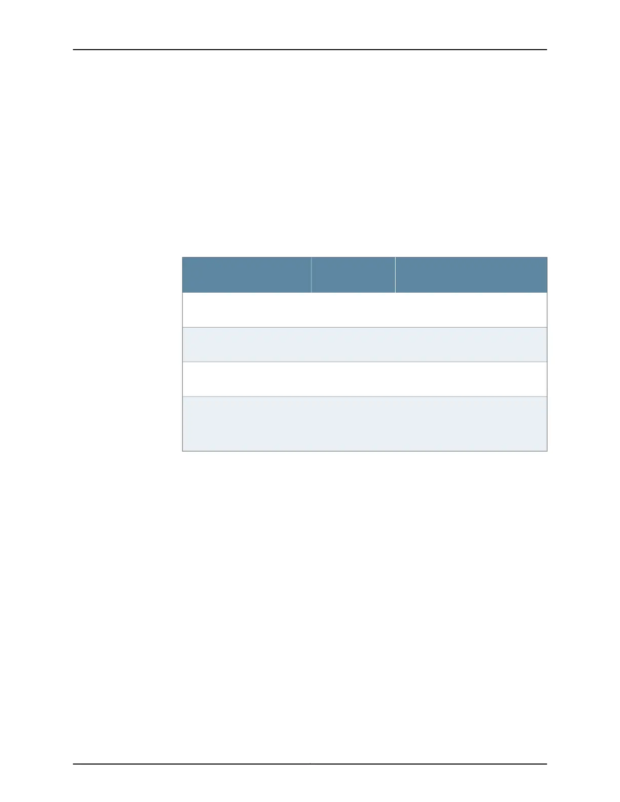
Table 27 on page 59 provides information about the clearance requirements for
maintaining optimum airflow and the distances to facilitate easy maintenance of the
services gateway.
Table 27: Clearance Requirements for the SRX550 High Memory Services
Gateway
Requirement for Clearance
Recommended
ClearanceLocation
Space for service personnel to remove
and install hardware components
8.7 in. (22 cm)Front of the chassis
Space for service personnel to remove
and install hardware components
17.4 in. (44.2 cm)Rear of the chassis
Space for cable management and
organization
2.5 in. (6.35 cm)Between front-mounting flange
and rack or cabinet edge
Space for the cooling system to
function properly and to maintain
unrestricted airflow around the chassis
6.0 in. (15.24 cm)Between both sides of the
chassis and any
non-heat-producing surface
such as a wall or cabinet side
Related
Documentation
• SRX550 High Memory Services Gateway Description on page 3
• SRX550 High Memory Services Gateway Cabinet Size and Clearance Requirements
on page 61
• Site Preparation Checklist for the SRX550 High Memory Services Gateway on page 47
• SRX550 High Memory Services Gateway Rack Size and Strength Requirements on
page 57
• General Site Installation Guidelines for the SRX550 High Memory Services Gateway
on page 49
59Copyright © 2016, Juniper Networks, Inc.
Chapter 7: Rack Requirements
 Loading...